Have you ever encountered this situation before?
- The blueprints were "perfect," but upon cutting the steel at the workshop, they discovered misaligned holes, incorrect heights, and bolts that didn't fit.
- When tested on the construction site, they didn't fit together, requiring on-site welding and cutting adjustments.
- The project was delayed, costs increased, and the quality of the joints was no longer as per the original design.
In steel construction, a small error can have big consequences. The good news is: most costly errors can be eliminated before production if you apply one thing correctly: modeling (3D/BIM) + a checklist
This article by CMC Architects shares how to design steel structures that are "100% accurate" in practice, and provides a checklist for checking before sending drawings to the factory—something many projects only realize the value of when it's already too late.
👉 What type of steel structure are you working on?
A. Factory/prefabricated steel frame
B. Townhouse/renovation/adding floors using steel
C. Canopy, glass roof, staircase, steel floor
Comment A/B/C so I can suggest a priority checklist based on your project type!
Why is a "100% fit" a crucial goal for steel structures?
Unlike reinforced concrete, which can be "expanded" by plastering, grouting, adjusting the reinforcement, etc., steel components are typically:
- prefabricated in the factory
- assembled on-site
- heavily dependent on the accuracy of the model and shop drawings.
Straight talk:
If the mistake starts in the modeling phase, it will lead to further mistakes in the factory, and by the time it reaches the construction site, the only option left is to "fix the problem."
But "firefighting" in steel construction often involves:
- on-site welding and cutting → reduced aesthetics, increased technical risks
- prolonged timelines → increased labor and machinery costs
- repeated repairs → loss of quality control during erection
How does modeling (3D/BIM) help ensure that steel components fit together properly during assembly?
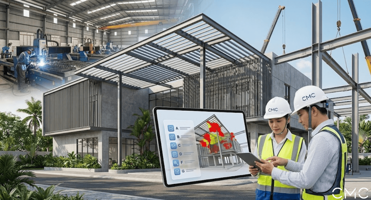
1) Anticipate a clash before cutting a piece of steel
The 3D model lets you see:
- Are there any bolts obstructing the beam-column intersection?
- Does the base plate have sufficient clearance for tightening?
- Do the bolt holes coincide with the holes of the connecting components?
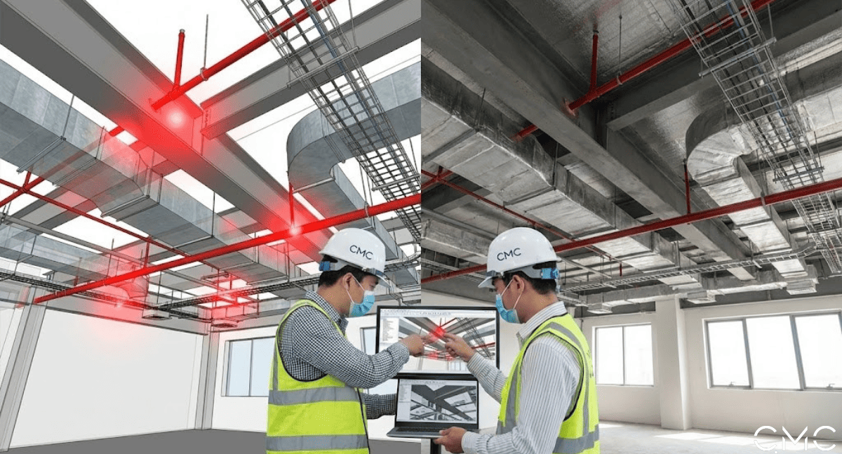
- Is there a conflict with MEP: air ducts, water pipes, cable trays, etc.?
2) Control tolerances and assembly logic
In addition to being "correctly sized," the model also helps control:
- the installation sequence
- lifting points, suspension points
- installation clearance, tool operation clearance
- expansion joints, settlement joints (if any)
3) Accurately calculate quantities, reduce unforeseen expenses
When modeling correctly, you can extract:
- section steel, steel plates, base plates
- number of bolts, washers
- weld length, paint/plating
→ helps to make a clear estimate and minimize unforeseen costs.
Pre-production inspection checklist (CMC suggested)
You can copy this checklist and give it to the design team/contractor/workshop for review before releasing the fabrication drawings.
A. Check the input data – If it's wrong here, the entire project will be wrong
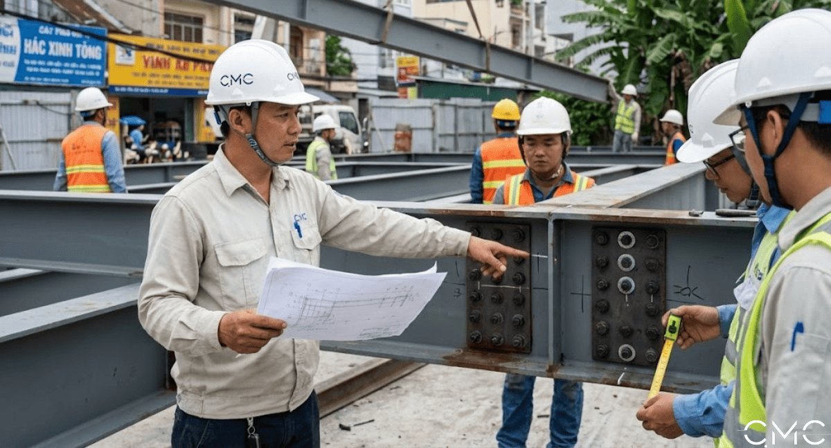
- Coordinate system, standard elevation (±0.000), and reference points have been finalized.
- Existing dimensions have been confirmed (especially for renovation projects).
- Load parameters and applicable standards have been agreed upon (TCVN/Eurocode/…).
- Scope has been agreed upon: what items are included in the steel structure (frame, roof, floor, stairs, railings…).
- Drawings/connection points with concrete, walls, foundations… (interface) have been prepared.
✅ Practical suggestion: For renovations, it's advisable to remeasure the existing condition using a laser/scan if possible. Steel is very sensitive to discrepancies in its current condition
B. Checking the 3D model – “Correct shape” is not enough, it must be “correctly assembled”
- All components have clear, non-duplicate component codes (marks).
- Check the correct orientation of beams/columns (section rotation, web/flange orientation).
- Check the elevation of beam ends, beam bottoms, steel floor slabs, and roof slope.
- Check installation clearance: sufficient space for tightening bolts and tools.
- Check clearances to prevent collisions with: walls, glass, ceilings, and MEP.
- Clash detection has been run between the steel structure and MEP/architecture.
- Check the erection logic: can the components be placed in position or are they "stuck"?
👉 Quick question: Are you using Tekla/Revit for modeling or creating 3D models using your own method? Each platform will have a different drawing output checklist
C. Check connections – Where 80% of "mismatch" errors occur
- Type of connection agreed upon: bolt/welding/combination
- Base plates of sufficient thickness, sufficient support area, and correct steel grade
- Bolt holes of correct diameter and standard (standard/oval drilling if necessary)
- Edge distance and pitch/gauge distance meet requirements
- Number of bolts, bolt strength grade, and bolt length are appropriate
- Consideration of actual bolt installation: are there any obstructions when inserting bolts?
- Weld inspection: length, dimensions, and position for ease of installation
- Inspection of position/length of stiffeners, stiffening ribs, and stiffeners
✅ Tip: Get it right from the start. Always check the bolt path and the position of the torque wrench/tightener. Many connections are calculated correctly but… cannot be tightened on the job site
D. Check the interface against the architecture
- Correct gaps for glass/panel/wall installation (especially canopies, facades, glass roofs)
- Finished elevation: floors, stairs, and doorways are not at the correct level.
- Left space for installation of coverings, moldings, trims, and spotlights.
- Handrail/balustrade mounting positions are finalized according to safety standards.
- Waterproofing check: roof-wall-gutter-metal/glass junctions.
E. Check the interface with MEP (electricity, water, air conditioning)
- Cable trays, air ducts, and water pipes do not penetrate beams/columns.
- Opening locations are agreed upon and clearly shown on the model.
- There is a plan for suspending MEP (Mechanical, Electrical, and Plumbing) from the steel structure (hangers, unistruts, etc.).
- Lighting, camera, and sprinkler locations have been finalized (avoiding contact with purlins and rafters).
F. Check the shop drawing and BOM (manufacturing drawing and materials list)
- The fabrication drawings include: dimensions, tolerances, welding symbols, and hole symbols.
- The BOM/NC list is complete and free of missing components, base plates, or bolts.
- Each component includes: code, length, cutting angle, number of holes, and hole location.
- The drawings clearly indicate the steel grade and paint/coating standard.
- Assembly drawings (GA/Erection drawing) are included.
✅ Suggestion: A "cross-checking" step between the design team, the workshop team, and the erection team should be conducted before issuing the IFC (Issued For Construction)
G. Practical Checklist Before Cutting Steel (Final Gate)
- Review the final 3D model and shop drawings (revision control).
- Finalize the assembly order, lifting plan, and transportation plan.
- Confirm site conditions: access roads, staging area, and crane location.
- Agree on acceptance standards: bolt tightening torque, weld inspection, painting/plating.
- Allocate for tolerances based on existing conditions (especially for renovation projects).
Practical example: Why does "modeling + checklist" actually save money?
Case (simulation): A steel and glass canopy on the facade of a townhouse
- If only 2D measurements are used, the steel cutting workshop will cut the steel according to "theoretical" dimensions.
- Upon installation at the construction site, it was discovered that the existing walls were misaligned and the height was uneven, causing the canopy to be "off-center".
- The quick fix solution: cutting, welding, and adjusting on-site, redoing the base plates – both unsightly and costly.
If modeling and pre-production testing are available:
- Measure existing conditions, create 3D models, and show actual connection points.
- Check glass mounting gaps and bolt positions.
- Check tolerance pins and shim/plate compensation.
→ Installation is quick, clean, aesthetically pleasing, and exactly as designed
Are you working on a canopy/glass roof or a steel frame for a factory building? I can suggest a detailed checklist for each type
Conclusion: "100% match" is not luck, it's a process
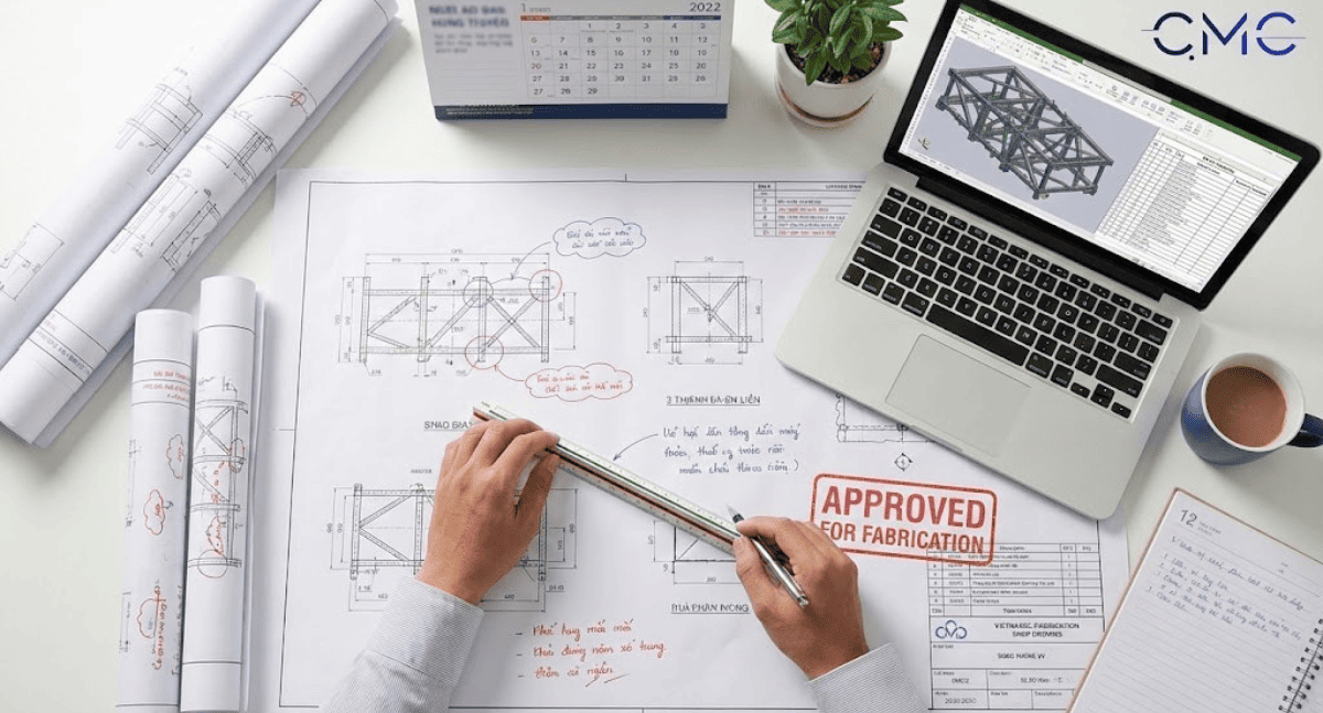
Beautiful and well-built steel structures don't come from "emergency work." They come from:
- Proper modeling
- Proper testing
- Proper release
- And proper coordination between design, workshop, and site
👉 If you would like CMC Architects to assist in reviewing your model/shop drawing before production, simply send us:
- Existing drawings/models (Revit/Tekla/IFC)
- Scope of steel work
- Production timeline
📩 Comment “STEEL CHECKLIST” or message CMC Architects to receive the checklist in file format and the pre-production error checking process.
In your opinion, the most common "mismatch" errors are:
1. Incorrect existing condition
2. Incorrect bolt/plate connections
3. MEP conflicts
4. Incorrect elevation
Comment 1/2/3/4 so I can analyze how to avoid each mistake!
- 📞 Hotline: 0936361299
- 📧 Email: cmc.vn1013@gmail.com
- 🌐 Website: https://cmcarchitects.com/
- 📍 Address: 79A Xuan La, Tay Ho, Hanoi