In a construction project, drawings are the "common language" that helps architects, engineers, investors, manufacturers, and construction teams understand the design concept correctly. However, not all types of drawings serve the same purpose.
Many people often confuse architectural drawings and engineering drawings. Some think that having only architectural drawings is enough to start construction immediately. But in reality, for a project to be implemented accurately, especially for items such as steel railings, steel staircases, handrails, steel door frames, ladders, louvers, panels, base plates, bolts, and connection details, engineering drawings play an extremely important role.
So, how do architectural drawings and engineering drawings differ? When are architectural drawings needed? When are detailed engineering drawings needed? Let's explore this further with CMC Architects Vietnam in the article below.
1. What are architectural drawings?
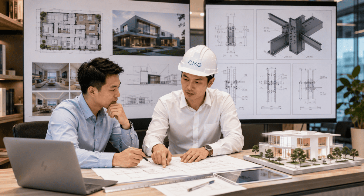
Architectural drawings are a type of drawing that represents the overall design concept of a building. These documents help viewers visualize the space, shape, function, style, and architectural layout of a project.
Architectural drawings typically focus on elements such as:
For example, with a townhouse, architectural drawings help the owner understand where the living room is located, how the staircase is arranged, what the facade will look like, where the windows will be placed for natural light, and whether the overall style of the building is modern, minimalist, or luxurious.
- Floor plan and spatial layout.
- Building elevation.
- Architectural section.
- Overall form.
- Design style.
- Location of doors, stairs, balconies, and corridors.
- Functional organization.
- Spatial proportions and aesthetic appeal.
Simply put, architectural drawings answer the question: what will the building look like and how will it be organized
2. What is a technical drawing
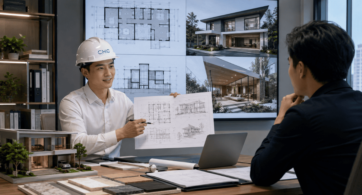
While architectural drawings help to express the overall concept and space, engineering drawings delve into the implementation, structure, dimensions, materials, and construction details.
Engineering drawings are crucial documents for the production, fabrication, installation, and quality control processes at the construction site or factory.
Engineering drawings typically show:
- Detailed dimensions.
- Installation elevation.
- Floor plans, elevations, and technical sections.
- Material specifications.
- Structural details.
- Connection details.
- Base plates, bolts, screws, welds.
- Manufacturing and installation tolerances.
- Technical notes.
- Component list if needed.
For architectural steel and metal items, technical drawings may include drawings of steel railings, steel staircases, steel door frames, louvers, panels, technical ladders, or detailed connection drawings.
Simply put, technical drawings answer the question: how will this item be manufactured, fabricated, and installed?
3. The biggest difference between architectural drawings and engineering drawings
The biggest difference lies in their intended use.
Architectural drawings focus on ideas, functionality, and aesthetics. Technical drawings, on the other hand, prioritize detail, accuracy, and practical construction feasibility.
In simpler terms:
Architectural drawings provide viewers with an overall view of the building, its design style, and spatial organization.
Technical drawings allow the manufacturer and construction team to know exactly what needs to be done, what materials to use, the dimensions, the connections, and the installation location.
For example, a steel staircase might be shown as part of an interior space or floor plan in an architectural drawing. However, to manufacture and install that staircase, a detailed technical drawing is needed, specifying the step dimensions, steel thickness, base plates, bolts, connections to the floor, railings, handrails, and installation heights.
Therefore, these two types of drawings are not interchangeable. They complement each other during the project implementation process.
4. Architectural drawings focus on the concept and experience of space
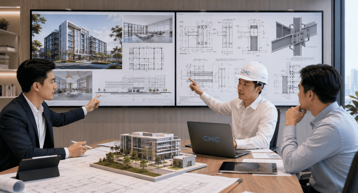
In building design, architectural drawings play a crucial role in shaping the initial concept. They help the investor and stakeholders understand how the building will be organized.
Architectural drawings typically focus on:
Functional use.
Spatial layout.
Movement within the building.
Facade form.
Architectural proportions.
Lighting and ventilation.
Overall aesthetics.
User experience and emotions.
This is a crucial part because a good structure not only needs to be sturdy, but also needs to meet usage requirements, be aesthetically pleasing, and create a comfortable feeling for users.
However, architectural drawings are often not detailed enough for the workshop or construction team to implement specialized items such as steel, mechanical, architectural metalwork, or complex connection details.
5. Technical drawings focus on accuracy and constructability
Technical drawings represent the transition from concept to construction. These drawings require high clarity, detail, and accuracy.
A good technical drawing should clearly demonstrate:
How is the item constructed?
What are the dimensions of each part?
What materials are used?
How are the connections to the structure made?
Are base plates, bolts, welding, anchor screws, or other accessories required?
What are the manufacturing and installation tolerances?
Are there any obstructions from structures, panels, MEP, or other items?
For steel structures, technical drawings are even more crucial because many details are pre-fabricated in the factory. If the drawings lack information or are unclear, components may be fabricated incorrectly, making installation difficult or requiring further modifications on site.
This not only wastes time but can also lead to increased costs and affect project timelines.
6. Why shouldn't you rely solely on architectural drawings for construction
Architectural drawings are very important, but relying solely on them for the construction of technical elements can easily lead to errors.
Some common problems include:
- Missing detailed dimensions.
- Material not clearly shown.
- No connection details.
- No base plates, bolts, or anchor points.
- Installation tolerances not shown.
- Actual elevation unclear.
- Insufficient information for fabrication workshop.
- The construction team must handle the work themselves on-site.
For example, architectural drawings might show the location of railings on balconies or staircases. However, to manufacture railings, it's necessary to know the handrail height, post spacing, steel bar cross-section, base plate location, number of bolts, floor connection method, and surface finish requirements.
If this information isn't translated into technical drawings, the manufacturing and installation process will face many risks.
7. Technical drawings help connect design, manufacturing, and construction
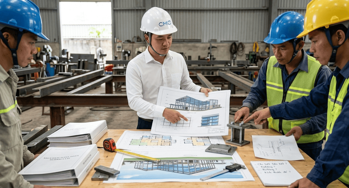
A clear set of technical drawings helps all parties work based on a single source of information.
For projects involving steel structures, technical drawings help:
Architects accurately communicate design ideas.
Engineers control the structure and connections.
The manufacturing workshop understands the correct dimensions and materials.
The construction team installs in the correct location.
The client can easily inspect the quality.
The project minimizes errors and unforeseen issues.
Technical drawings are not just documents for "completing paperwork." They are tools that help projects run more efficiently from the design phase to production, construction, and handover.
The clearer the drawing, the fewer questions, revisions, and rework will be required.
8. The role of AutoCAD 2D in technical drawings
In technical drawing implementation, AutoCAD 2D remains a very important tool. AutoCAD helps to accurately represent every line, dimension, note, plan, elevation, section, and connection detail.
For steel structures, AutoCAD 2D is particularly suitable for implementation:
- Shop drawings.
- Fabrication drawings.
- Assembly drawings.
- Base plate details.
- Bolt details.
- Weld details.
- Technical sections.
- Component quantity table.
- Material and surface finish notes.
A good AutoCAD 2D drawing needs to be clean, with clear layers, full dimensions, easy-to-understand notes, and consistency across views.
This is the foundation that helps the workshop and construction team read the drawing faster, understand it better, and implement it more accurately.
9. The role of BIM in coordinating architectural and engineering drawings.
In addition to AutoCAD 2D, BIM helps inspect construction projects in 3D space and supports coordination between multiple disciplines.
BIM makes it easier for all parties to inspect:
Location of the item within the overall project.
Conflicts between architecture, structure, and MEP.
Relationship between stairs, railings, panels, louvers, door frames, and technical systems.
Actual installation space.
Elevation and location of components.
Scope and volume of work.
BIM doesn't completely replace 2D drawings, but it helps identify issues that 2D drawings struggle to fully represent. When combined with AutoCAD 2D, the drawing documentation becomes both detailed and easy to manage overall.
This is a highly effective combination in projects with many technical aspects or requiring high precision.
10. How should architectural drawings and engineering drawings be coordinated
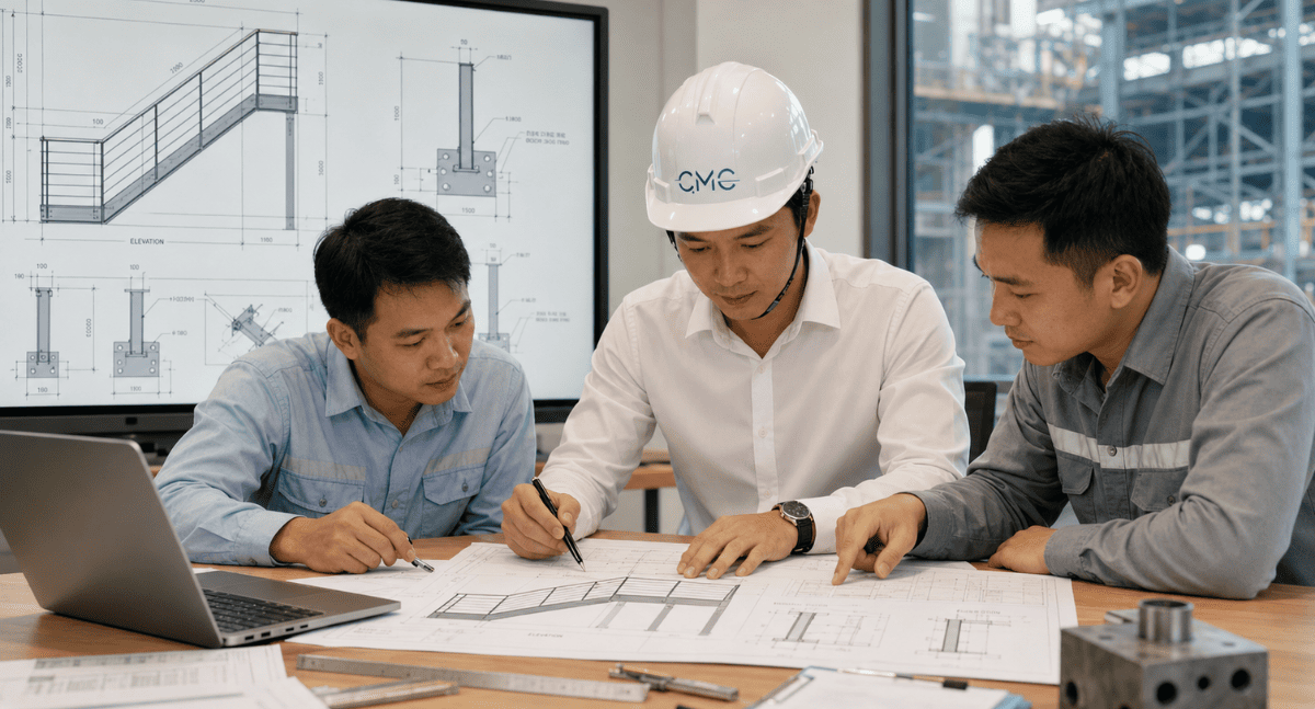
For the project to be implemented effectively, architectural drawings and engineering drawings need to be closely coordinated.
The coordination process should include:
Step 1: Understand the architectural concept
Before implementing the design, the design team needs to thoroughly understand the architectural concept, functionality, aesthetics, and usage requirements of the building.
Step 2: Identify the items requiring technical implementation.
Items requiring complex fabrication, installation, or construction should be documented in detailed technical drawings.
For example:
Steel railings.
Steel staircases.
Handrails.
Technical ladders.
Steel door frames.
Louvers.
Panels.
Base plates and connecting details.
Step 3: Check the dimensions, materials, and actual conditions
Before implementing the technical drawings, it is necessary to check the actual dimensions, materials, elevations, surrounding structures, and construction conditions
Step 4: Create technical drawings using AutoCAD 2D
AutoCAD 2D helps to clearly show machining details, assembly, construction, connections, and technical notes
Step 5: Use BIM for overall review if needed
For complex projects, BIM helps with collision detection, installation space management, and coordination across multiple disciplines
Step 6: Review and hand over the documents
Before handover, it is necessary to check the consistency between the drawings, versions, dimensions, materials, notes, and connection details.
When the coordination process is clear, architectural and engineering drawings will support each other better, helping to reduce errors and ensure a more professional project implementation
11. Common mistakes when confusing architectural drawings and engineering drawings
In practice, many projects encounter difficulties because the roles of these two types of drawings are not clearly distinguished
Some common mistakes include:
Using architectural drawings to request fabrication from the workshop.
Missing shop drawings for steel components.
No detailed connection drawings.
No actual dimensions checked before production.
No detailed cross-sections.
Missing material and surface finish information.
2D drawings do not match the BIM model.
Architectural changes have occurred, but the engineering drawings have not been updated.
The workshop and the construction site receive information from two different sources.
These errors can cause project delays, increased costs, and affect the quality of completion.
Therefore, correctly distinguishing and coordinating architectural drawings and engineering drawings is essential.
12. How does CMC Architects Vietnam support the implementation of technical drawings

At CMC Architects Vietnam, we understand that a beautiful building comes not only from its architectural concept, but also from a clear, accurate, and practical technical drawing system.
CMC Architects Vietnam supports the implementation of technical drawings for many projects such as:
Steel railings.
Handrails.
Steel staircases.
Technical ladders.
Steel door frames.
Louvers.
Panels.
Secondary steel frames.
Base plates, bolts, and connecting details.
Other architectural metal items.
During the implementation process, we focused on:
Receive and analyze design requirements.
Verify input information.
Develop clear 2D AutoCAD drawings.
Utilize BIM to support overall verification when needed.
Control dimensions, elevations, and materials.
Check connection details.
Ensure consistency between drawings.
Review documentation before handover.
CMC Architects Vietnam's goal is to create a set of architectural drawings that are easy to read, understand, produce, and construct, helping clients minimize errors and improve project implementation efficiency.
13. Conclusion
Architectural drawings and engineering drawings are both crucial in a construction project, but each type plays a different role.
Architectural drawings help to express the overall concept, function, space, and aesthetics of the building.
Engineering drawings help to detail the structure, dimensions, materials, connections, and practical construction methods.
If architectural drawings are the foundation of the concept, then engineering drawings are the bridge that accurately and professionally transforms that concept into a real-world project.
Have you ever encountered a situation where the architectural drawings are beautiful but lack technical information during construction?
Does your project require more detailed engineering drawings to support production and installation?
If you are looking for a company to assist with AutoCAD 2D, BIM, and shop drawings for architectural steel and metal elements, contact CMC Architects Vietnam for consultation and support in your project.
CMC Architects Vietnam – Partnering with you from architectural concept to clear, accurate, and professional technical drawings.