Why Is It Important to Align Information Before Starting Technical Drawings?
In the process of designing and developing technical drawings, there is one step that may seem simple but plays a decisive role in the overall quality of the drawing package: aligning all information before starting the drawing process.
Many projects encounter difficulties not because the design team lacks capability, nor necessarily because the project itself is too complex. In many cases, the problem starts from unclear input information, continuously changing requirements, or different parties having different understandings of dimensions, materials, scope of work, or handover standards.
This is especially important for steel and architectural metalwork items such as steel railings, handrails, steel staircases, technical ladders, steel door frames, louvers, panels, base plates, bolts, and connection details. Even one piece of inconsistent information can cause drawings to be revised multiple times, lead the fabrication workshop to misunderstand the requirements, or create difficulties for the installation team on site.
So why is it necessary to align information before developing drawings? What information needs to be clarified? And how can this step help save time and cost for the project? Let’s explore the details with CMC Architects Vietnam in the article below.
1. Information Alignment Is the Foundation Before Drawing

Before starting any drawing work, the design team needs to clearly understand what they are drawing, what purpose the drawing serves, and at which project stage the drawing will be used.
A drawing package may be used for:
-
Presenting a design proposal.
-
Technical review.
-
Approval submission.
-
Fabrication at the workshop.
-
Installation on site.
-
Coordination between disciplines.
-
Handover to clients or partners.
Each purpose requires a different level of detail. For example, a drawing used to present an initial concept may focus on the overall layout and composition. However, a drawing used for fabrication must clearly show dimensions, materials, connection details, base plates, bolts, welds, and tolerances.
Therefore, if the purpose of the drawing is not aligned from the beginning, the drawing process can easily go in the wrong direction. The drafter may spend a lot of time adding details, but those details may not be what the client or construction team actually needs.
2. Unclear Information Often Leads to Repeated Revisions
One of the most common issues in drawing development is repeated revision. The reason does not always come from technical mistakes. In many cases, it comes from incomplete or unclear initial information.
For example:
-
Opening dimensions have not been confirmed.
-
Finished floor levels have not been agreed upon.
-
Materials have not been finalized.
-
The drawing scope is unclear.
-
Installation positions change after the drawings have already been developed.
-
Architectural, structural, and MEP drawings are not synchronized.
-
The client has not confirmed the final design option.
-
The fabrication workshop needs additional information that was not included in the initial drawings.
When these pieces of information change after the drawings have already been developed, the design team must update plans, elevations, sections, connection details, material schedules, and sometimes even the BIM model.
This not only takes additional time for the design team but also affects the overall project schedule.
3. Information Alignment Helps Reduce Errors in Technical Drawings

Technical drawings require a high level of accuracy. Every line, dimension, note, and symbol has a specific meaning for the fabrication workshop and the construction team.
If the input information is unclear, the drawings may include errors such as:
-
Incorrect overall dimensions.
-
Incorrect installation levels.
-
Missing connection details.
-
Missing base plates, bolts, or welds.
-
Mismatch with the actual structural conditions.
-
Unsuitable specifications for the selected materials.
-
Incorrect door opening direction, installation direction, or accessory location.
-
Missing clearance required for construction.
For steel items, many components are fabricated in advance at the workshop. If the drawings are incorrect, the fabricated products may also be incorrect. Once they are delivered to the site, adjustments become more difficult, more costly, and may affect the final quality of the project.
Aligning information from the beginning helps reduce these risks and creates a solid foundation for more accurate drawing development.
4. The Scope of Work Must Be Clarified Before Drawing
One of the most important things to clarify before starting the drawing process is the scope of work.
The design team needs to define:
-
Which items require drawing development?
-
What level of detail is required?
-
Are shop drawings needed?
-
Is a material schedule required?
-
Is BIM coordination required?
-
Which parts are within the scope of CMC Architects Vietnam?
-
Which parts will be provided by the client, contractor, or another party?
-
Will the drawings be used for reference, approval, or construction?
For example, for a steel staircase item, the scope may include general arrangement drawings, tread details, railings, handrails, base plates, bolts, connections to the floor, and installation levels. However, if the initial requirement is only for a design proposal drawing, the level of detail will be different from drawings used for fabrication.
When the scope of work is clearly aligned, the design team can control the workload more effectively, and the client can also evaluate the deliverables more accurately.
5. Dimensions and Actual Site Conditions Must Be Confirmed

Dimensions are a core element of technical drawings. Before developing drawings, it is necessary to check and align all information related to actual dimensions.
The information that should be clarified includes:
-
Overall dimensions of the item.
-
Opening dimensions.
-
Height, width, and length.
-
Finished floor levels.
-
Spacing between components.
-
Locations of columns, beams, walls, panels, or related structures.
-
Installation clearances.
-
Tolerances for fabrication and construction.
-
Whether actual site measurement is required before mass fabrication.
For items such as steel door frames, railings, louvers, or panels, actual site dimensions may differ from the original design drawings. If these dimensions are not checked carefully, the fabricated products may not fit the installation positions.
Therefore, aligning dimensions and actual site conditions helps the drawings reflect site conditions more accurately and reduces construction risks.
6. Materials, Specifications, and Surface Finishes Must Be Agreed Upon
A technical drawing must not only show correct dimensions, but also clearly indicate materials. If the materials have not been agreed upon, the drawing may lack the necessary basis to show detailed specifications.
For steel items, the following information should be clarified:
-
Type of steel to be used.
-
Section dimensions.
-
Material thickness.
-
Steel grade or technical standard, if applicable.
-
Paint, galvanizing, stainless steel, powder coating, or anti-rust treatment.
-
Anti-corrosion requirements.
-
Fire resistance or impact resistance requirements, if required by the project.
-
Color and surface finish requirements.
For example, even for the same steel railing item, the drawing details, fabrication requirements, and finish notes may vary depending on whether the material is hot-dip galvanized steel, stainless steel, or powder-coated steel.
Aligning materials before drawing development helps the fabrication workshop understand the requirements correctly and avoids changes after the drawings have already been issued.
7. Drawing Presentation Standards Must Be Aligned
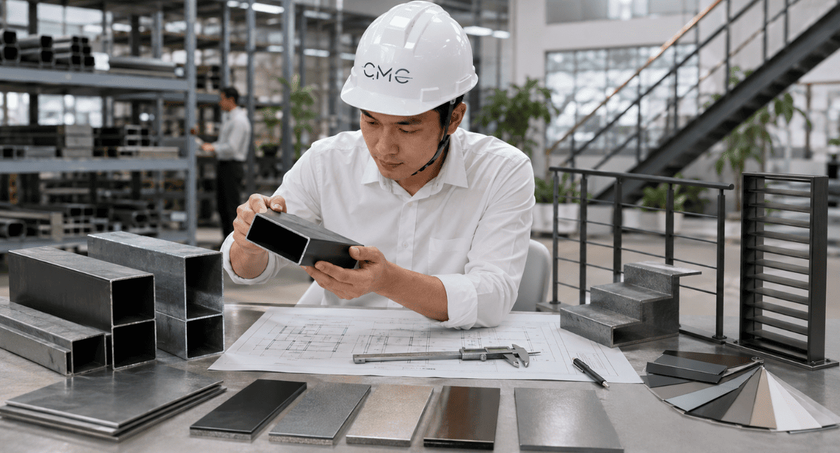
Each project may have different drawing presentation standards. This is especially important for projects involving Japanese partners or international clients, where clarity, consistency, and information control are often highly required.
Before starting the drawing process, the following elements should be aligned:
-
Drawing paper size.
-
Drawing scale.
-
File naming rules.
-
Drawing numbering rules.
-
AutoCAD layer standards.
-
Material symbols.
-
Weld, bolt, and base plate symbols.
-
Dimensioning method.
-
Language used in the drawings.
-
Handover standards for PDF, DWG, or BIM model files.
-
Revision rules and revision history.
When drawing presentation standards are agreed upon, the drawing package becomes more professional, easier to review, and less likely to cause confusion during coordination between different parties.
8. Information Alignment Helps AutoCAD 2D Work More Effectively
In technical drawing development, AutoCAD 2D is an essential tool for showing detailed plans, elevations, sections, dimensions, technical notes, and connection details.
However, AutoCAD is only truly effective when the input information is already clear.
When information is properly aligned, AutoCAD 2D drawings can accurately show:
-
Component dimensions.
-
Installation levels.
-
Technical sections.
-
Base plate details.
-
Bolt locations.
-
Welds.
-
Material specifications.
-
Finish notes.
-
Component schedules.
On the other hand, if the input information keeps changing, AutoCAD drawings will need to be revised repeatedly. This can easily create inconsistencies between different views and reduce the efficiency of the drawing process.
9. Information Alignment Helps BIM Coordination Become More Accurate
In addition to AutoCAD 2D, BIM helps check spatial relationships, detect clashes, and coordinate between multiple disciplines within a project.
BIM can support:
-
Checking the position of items within the overall model.
-
Detecting clashes with structure or MEP systems.
-
Checking installation clearances.
-
Checking levels and component positions.
-
Coordinating between architecture, structure, and steel items.
-
Helping clients and construction teams visualize the design solution more easily.
However, BIM also requires clear input data. If information about dimensions, materials, positions, or scope has not been aligned, the BIM model may not accurately reflect the actual project requirements.
Therefore, aligning information before modeling or BIM coordination helps make the checking process more effective and reduces discrepancies between the model and 2D drawings.
10. Information That Should Be Confirmed Before Drawing Development
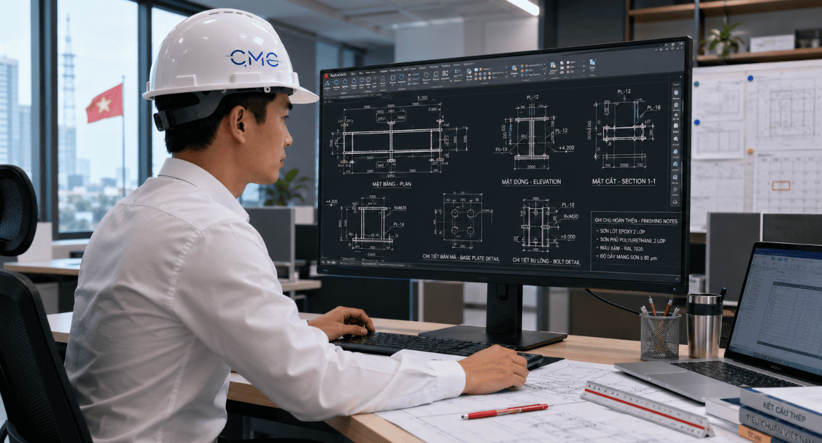
To make the drawing development process smoother, an input information checklist should be prepared before starting.
The information that should be confirmed includes:
-
Purpose of the drawings.
-
Scope of items to be developed.
-
Latest architectural, structural, and MEP drawings.
-
Related dimensions and levels.
-
Actual site conditions.
-
Materials and technical specifications.
-
Drawing presentation standards.
-
Drawing language.
-
Handover file formats.
-
Delivery deadline.
-
Person in charge of feedback and confirmation.
-
Update procedure when changes occur.
This checklist helps all parties reduce missing information and creates a clear working basis from the beginning.
11. Benefits of Aligning Information Before Drawing
Aligning information before developing drawings brings many practical benefits to the project.
Reducing Revision Time
When requirements are clear, the design team can work in the right direction from the beginning and reduce repeated revisions.
Reducing Errors in the Drawing Package
Complete input information helps the drawings become more accurate, more consistent, and easier to check.
Supporting the Fabrication Workshop More Effectively
The workshop can clearly understand dimensions, materials, specifications, and connection details in order to fabricate components accurately.
Supporting Smoother Construction
The construction team can use clear drawings to install components in the correct positions, at the correct levels, and according to the required technical standards.
Reducing Additional Costs
When errors are minimized from the drawing stage, the project can reduce the risk of cutting, reworking, or handling unexpected issues on site.
Increasing Professionalism
A clear working process helps clients, partners, and related parties feel more confident about the quality of the drawing package.
12. How Does CMC Architects Vietnam Control Information Before Drawing Development?

At CMC Architects Vietnam, we understand that a good drawing does not begin with drafting operations. It begins with understanding and aligning the right information.
During the technical drawing development process, CMC Architects Vietnam focuses on:
-
Receiving and analyzing project requirements.
-
Checking input drawings.
-
Clarifying the scope of items to be developed.
-
Checking dimensions, levels, materials, and actual site conditions.
-
Discussing unclear points before starting the drawing process.
-
Applying AutoCAD 2D to develop detailed drawings.
-
Applying BIM to support overall checking if required by the project.
-
Controlling versions and updating changes.
-
Reviewing the drawing package before handover.
With experience in technical drawing design, AutoCAD 2D, BIM, shop drawings, and steel – architectural metalwork items, CMC Architects Vietnam always aims to create drawing packages that are clear, easy to read, easy to fabricate, and easy to install.
13. Conclusion
Aligning information before developing drawings is a very important step in every construction project. It is the foundation that helps the design team understand the requirements correctly, develop accurate drawings, and support a smoother fabrication and construction process.
A high-quality drawing does not depend only on the ability to use AutoCAD or BIM. It also depends on whether the input information is clear, complete, and consistent.
Before starting drawing development, ask yourself:
Has the purpose of the drawing been clarified?
Has the scope of work been agreed upon?
Have the dimensions, materials, and levels been confirmed?
Are the architectural, structural, and MEP drawings synchronized?
Have the drawing handover standards been clarified?
If these pieces of information are still unclear, the project should be reviewed again before moving into the detailed drawing development stage.
If you are looking for a professional partner to support technical drawing design, AutoCAD 2D, BIM, and shop drawings for steel and architectural metalwork items, please contact CMC Architects Vietnam for consultation and project support.
CMC Architects Vietnam – Supporting your project from information alignment to a clear, accurate, and professional technical drawing package.
Contact Information
Address: 79A Xuan La, Tay Ho, Hanoi
Hotline: 0936361299
Email: cmc.vn1013@gmail.com
Website: cmcarchitects.com