In industrial buildings, factories, technical areas, machine rooms, rooftops, and maintenance zones, a technical ladder may look like a simple steelwork item. However, in reality, it requires a high level of accuracy in drawing development.
A technical ladder does not only need the correct shape. More importantly, the drawing must clearly show the installation position, levels, dimensions, rung spacing, base plates, bolts, connections, working clearances, and technical notes. Especially when the drawing is developed in AutoCAD 2D, every piece of information must be presented clearly so that the fabrication workshop and installation team can understand, manufacture, install, and inspect it correctly.
If the technical ladder drawing lacks important information or does not clearly show critical positions, fabrication errors may occur, the installation may not match actual site conditions, or rework may be required on site.
So, in an AutoCAD 2D drawing for a technical ladder, which positions need to be clearly shown? Let’s explore this topic in detail with CMC Architects Vietnam.
1. What Is a Technical Ladder?
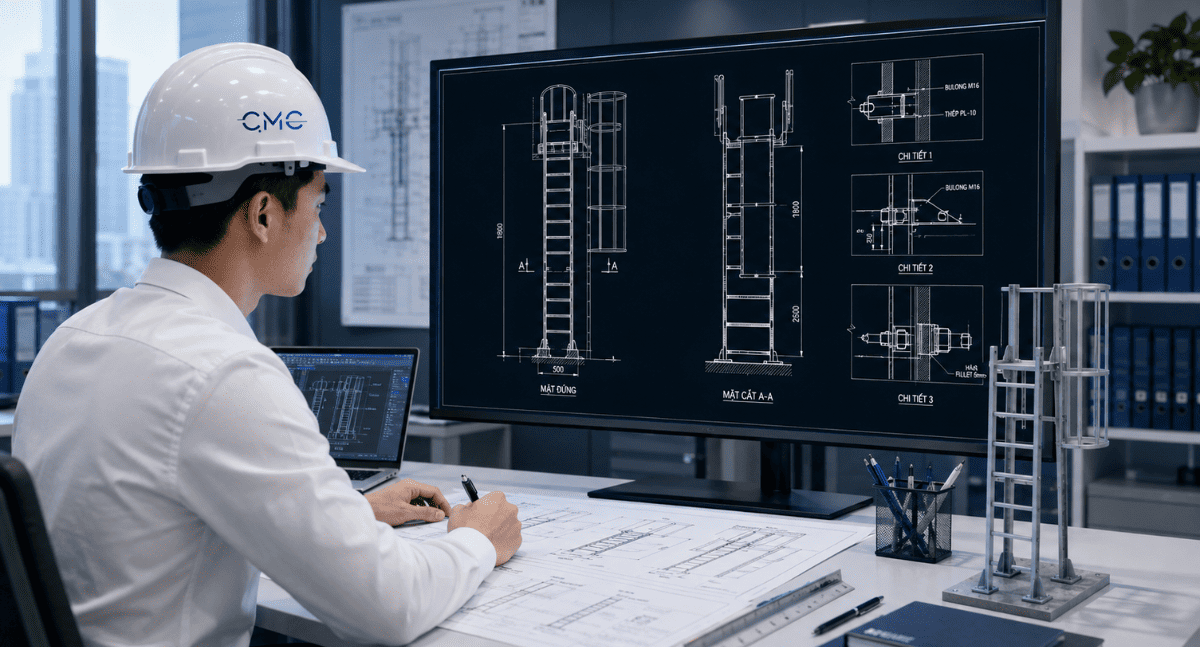
A technical ladder is a type of ladder used for access, inspection, operation, or maintenance in technical areas of a building. Unlike standard staircases used for daily circulation, technical ladders are usually installed in specialized locations such as:
- Factory rooftops.
- Machine rooms and electrical rooms.
- Tank, silo, or equipment areas.
- Outdoor technical systems.
- Equipment operation zones.
- MEP maintenance areas.
- Vertical access points for technical operation.
Because technical ladders are directly related to operation, maintenance, and safety, their drawings must be developed carefully, completely, and clearly. In this process, AutoCAD 2D remains an important tool for presenting detailed information for fabrication and installation.
2. Why Must Technical Ladder Positions Be Clearly Shown in AutoCAD 2D Drawings?
AutoCAD 2D drawings are used directly by fabrication workshops to cut steel, weld components, drill holes, fabricate base plates, prepare bolts, and hand over finished steel items. They are also used by installation teams to compare the fabricated product with actual site conditions.
If important positions are not clearly shown, several issues may occur:
- The ladder may be installed in the wrong location.
- Rung spacing may be inconsistent or incorrect.
- Base plates may not match the prepared structure.
- Bolt holes may be drilled in the wrong position.
- The clearance between the ladder and the wall may not be enough for safe use.
- The starting or ending point of the ladder may be unsuitable.
- The ladder may clash with beams, pipes, cable trays, or MEP equipment.
- Quality inspection after fabrication may become difficult.
For steelwork items, a small drawing error can lead to major issues during fabrication and installation. Therefore, clearly showing key positions in AutoCAD 2D drawings not only makes the drawing easier to read, but also helps reduce project risks, save time, and improve professionalism.
3. Overall Position of the Technical Ladder in the Building

The first position that must be clearly shown is the overall position of the technical ladder within the building.
On the plan view, the drawing should show where the ladder is located, which grid lines it relates to, and how it connects to nearby walls, columns, beams, floors, roofs, or technical equipment. This is the basic information needed to define the installation scope and the ladder’s relationship with the surrounding space.
Important information includes:
- Ladder position on the overall plan.
- Distance from the ladder to building grid lines.
- Distance to nearby walls, columns, beams, or equipment.
- Access direction to the ladder.
- Working space in front of the ladder.
- Relationship with doors, maintenance floors, rooftops, or technical zones.
When the overall position is clearly shown, the installation team can easily identify the correct installation area and avoid confusing one ladder with another in the same project.
4. Starting Point and Ending Point of the Technical Ladder
In technical ladder drawings, the starting point and ending point are two extremely important locations.
The starting point is usually related to the floor, slab, base, or the area where users access the ladder. The ending point is usually related to a maintenance floor, rooftop, technical door, platform, or upper operation area.
The drawing should clearly define:
- The level where the ladder starts.
- The level where the ladder ends.
- The distance from the first rung to the floor.
- The distance from the last rung to the platform.
- The position of hand grips or extended ladder parts, if any.
- Whether the access area at the top and bottom is safe and convenient.
If the starting and ending points are not clear, the ladder may become too high, too low, or inconvenient for actual use. This is a common mistake when the drawing only focuses on the overall shape without carefully checking levels and access conditions.
5. Installation Levels of the Technical Ladder

Level information is essential in AutoCAD 2D drawings for technical ladders. A drawing that only shows the overall height but does not show specific levels can still cause misunderstanding during installation.
The drawing should show:
- Starting floor level.
- Ending floor or platform level.
- Level of the first rung.
- Level of the last rung.
- Level of connection base plates.
- Top level of the ladder.
- Level of handrails or extended ladder parts, if any.
- Levels related to beams, roofs, platforms, or technical equipment.
Clear level information helps the installation team accurately locate the ladder in the vertical direction. In technical areas with multiple MEP systems, level control also helps avoid clashes with pipes, cable trays, ducts, or operating equipment.
6. Spacing Between Ladder Rungs
Rung spacing is one of the most important details in technical ladder drawings. It directly affects user convenience and safety.
The drawing should clearly show:
- Spacing between each rung.
- Total number of rungs.
- Position of the first rung.
- Position of the last rung.
- Rung dimensions.
- Rung shape: round bar, square bar, steel tube, or other material.
- Useful width of each rung.
If rung spacing is inconsistent or not clearly dimensioned, fabrication errors may occur. During actual use, uneven spacing can make the ladder uncomfortable and may even create safety risks when users climb up or down.
7. Ladder Width and Distance Between Two Vertical Members

In addition to height, the ladder width must also be clearly shown in AutoCAD 2D drawings.
The ladder width affects usability, working space, and fabrication method. If the ladder is too narrow, it becomes inconvenient to climb. If it is too wide, it may not fit the installation area or may increase material usage unnecessarily.
The drawing should show:
- Overall ladder width.
- Distance between the two vertical members.
- Specification of vertical members.
- Specification of horizontal rungs.
- Clearance on both sides of the ladder.
- Relationship between ladder width and installation space.
This information is important for the fabrication workshop to manufacture the ladder frame correctly and for the installation team to check the available space before installation.
8. Distance From the Ladder to the Wall or Rear Structure
One important detail that is often overlooked is the distance from the ladder to the wall, column, panel, or rear structure.
This distance directly affects foot clearance, climbing comfort, and the connection method. If the distance is too small, users may find it difficult to step on the rungs. If it is too large, the connection details may require reinforcement or a different base plate design.
The drawing should show:
- Distance from the ladder centerline to the wall.
- Distance from the rung surface to the rear structure.
- Distance from base plates to the wall edge or slab edge.
- Working clearance in front of and behind the ladder.
- Nearby obstructions such as pipes, cable trays, beams, doors, or equipment.
This information is especially important when the ladder is installed in a technical area, where the surrounding space is often limited and many systems are located nearby.
9. Base Plate Positions
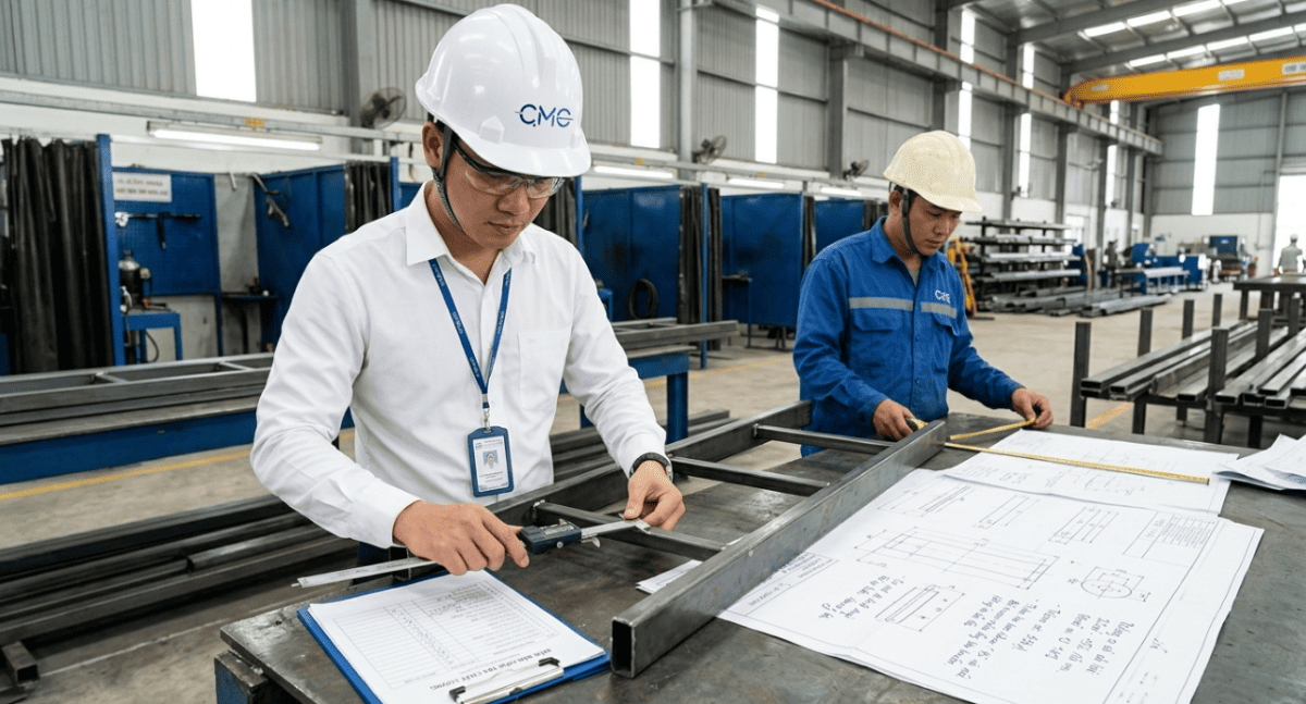
Base plates are key components that determine how the technical ladder is fixed to the building. Therefore, their positions must be clearly shown in AutoCAD 2D drawings.
Required information includes:
- Base plate position on the plan view.
- Base plate position on the elevation view.
- Base plate dimensions.
- Base plate thickness.
- Number of base plates.
- Spacing between base plates.
- Distance from base plates to slab edges, wall edges, or structural grid lines.
- Base plate orientation.
- Fabrication notes for base plates.
If base plates are not clearly shown, the workshop may drill holes incorrectly, weld components in the wrong position, or fabricate details that do not match actual site conditions.
10. Bolt Positions, Drilling Holes, and Anchoring Method
Bolts, drilling holes, and anchoring methods must be shown in detail to ensure that the technical ladder is installed firmly and safely.
The drawing should clearly show:
- Type of bolts used.
- Bolt diameter.
- Number of bolts.
- Spacing between bolt holes.
- Distance from bolt holes to base plate edges.
- Anchoring depth, if required.
- Hole positions on the base plate.
- Connection method to concrete, steel, or panels.
- Notes for tightening bolts, washers, and nuts if necessary.
For technical ladder drawings, bolt positions should not be shown only with general symbols. Specific dimensions should be provided so that the fabrication workshop and installation team can check them easily.
11. Weld Positions and Fabrication Details
In addition to bolts, many parts of a technical ladder are connected by welding. Therefore, the drawing should clearly show weld positions, weld length, and post-welding treatment requirements.
Important information includes:
- Weld positions between rungs and vertical members.
- Weld positions between vertical members and base plates.
- Weld positions for protective cages, if any.
- Weld length or welding range.
- Grinding or smoothing requirements.
- Weld inspection requirements.
- Surface treatment after welding.
If weld information is not clearly shown, fabrication quality may vary between components. For visible details or areas requiring good appearance, notes about weld finishing become even more important.
12. Protective Cage or Safety Frame Positions, If Required
Some technical ladders include a protective cage, safety rings, or fall protection structure depending on project requirements and usage conditions. When this element is included, it should be shown separately in the AutoCAD 2D drawing, not described only in general notes.
The drawing should clearly show:
- Starting position of the protective cage.
- Ending position of the protective cage.
- Spacing between safety rings.
- Dimensions of the safety rings.
- Distance from the cage to the ladder.
- Connection positions between the cage and ladder.
- Material specification of the protective cage.
- Fabrication and finishing notes.
If this information is missing, the protective cage may be fabricated with incorrect dimensions, become difficult to assemble, or fail to provide proper working clearance.
13. Access Position, Clearance, and Working Space
A technical ladder drawing should not only show the ladder itself. It should also show the surrounding space to confirm that the ladder can be used safely and practically.
The following positions should be checked:
- Clearance in front of the ladder.
- Clearance on both sides of the ladder.
- Space at the starting point.
- Space at the ending point.
- Area where users step out from the ladder.
- Nearby doors, railings, handrails, or equipment.
- Distance to surrounding MEP systems.
This information helps ensure that the drawing is not only dimensionally correct, but also suitable for actual operation and maintenance.
14. Relationship With MEP Systems and Surrounding Structures
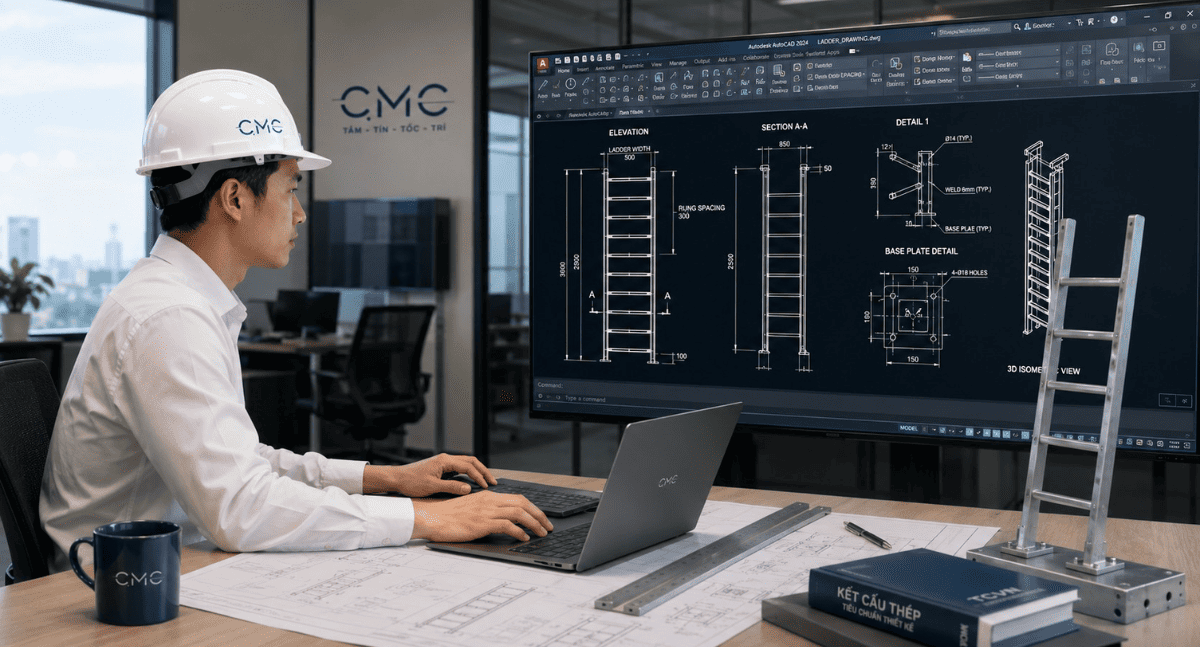
In industrial buildings, technical ladders are often installed near pipes, cable trays, ducts, machinery, steel beams, steel columns, or panels. Therefore, the drawing should check and show the relationship between the ladder and surrounding systems.
AutoCAD 2D drawings should clarify:
- Whether the ladder clashes with MEP systems.
- Distance to pipes, cable trays, or ducts.
- Position of nearby beams, columns, floors, or panels.
- Whether the ladder direction needs to be adjusted.
- Whether base plate or connection positions need to be changed.
- Whether any location needs to be checked on site before fabrication.
When combined with BIM, the technical team can check the overall relationship more effectively and reduce the risk of clashes before issuing fabrication drawings.
15. Technical Notes and Tolerance Information
A good technical ladder drawing should not include only views and dimensions. It also needs clear technical notes so that all parties can understand the requirements correctly.
Useful notes may include:
- Material specifications.
- Steel thickness.
- Painting, galvanizing, or anti-rust requirements.
- Weld finishing requirements.
- Fabrication tolerances.
- Installation tolerances.
- Positions that must be checked on site before fabrication.
- Notes for transportation and installation.
- Safety notes if required by the project.
Technical notes turn the drawing into a complete production document and help prevent the workshop or site team from making assumptions.
16. The Role of AutoCAD 2D in Technical Ladder Drawings
AutoCAD 2D plays an important role in developing technical ladder drawings because it helps present detailed information in a clear, readable, and handover-friendly format.
AutoCAD 2D can be used to show:
- Ladder location plan.
- Overall elevation.
- Section details.
- Base plate details.
- Bolt details.
- Weld details.
- Protective cage details.
- Component dimensions.
- Installation levels.
- Technical notes.
- Material schedules.
For fabrication workshops and installation teams, a clear AutoCAD 2D drawing helps them quickly understand the ladder structure, check dimensions, and proceed with the work more efficiently.
17. The Role of BIM in Checking Technical Ladder Positions
BIM does not completely replace AutoCAD 2D drawings, but it provides strong support in checking the overall position of technical ladders before detailed drawings are developed.
BIM helps check:
- Ladder position in 3D space.
- Clashes with structure, MEP systems, or equipment.
- Working clearances.
- Installation levels.
- Relationship between the ladder and surrounding elements.
- Accessibility for operation and maintenance.
When AutoCAD 2D and BIM are coordinated properly, technical ladder drawings can achieve both detailed clarity and strong overall project control.
18. How CMC Architects Vietnam Supports Technical Ladder Drawing Development
At CMC Architects Vietnam, we understand that technical ladder drawings require clarity, accuracy, and practicality for real fabrication and installation.
In our drawing development process, CMC Architects Vietnam focuses on:
- Reading and analyzing related architectural, structural, and MEP drawings.
- Accurately identifying the installation position of the technical ladder.
- Checking levels, distances, dimensions, and actual site conditions.
- Developing clear and readable AutoCAD 2D drawings.
- Showing complete plans, elevations, sections, and connection details.
- Clarifying base plates, bolts, welds, and materials.
- Checking consistency between different drawing views.
- Applying BIM to support overall checking when needed.
- Reviewing the drawing package before handover.
In addition to technical ladders, CMC Architects Vietnam also supports drawing development for many other steelwork items such as steel railings, handrails, steel staircases, steel door frames, louvers, panels, base plates, bolts, and connection details.
Our goal is to deliver drawing packages that are clear, accurate, easy to fabricate, easy to install, and suitable for the actual requirements of each project.
19. Conclusion

Technical ladders must be carefully developed in AutoCAD 2D drawings. To support fabrication and installation effectively, important positions such as overall location, starting point, ending point, levels, rung spacing, base plates, bolts, welds, protective cage, working clearances, and relationships with surrounding systems must be shown clearly.
A good technical ladder drawing helps the fabrication workshop produce components correctly and helps the installation team install them accurately, reduce errors, and improve project quality.
Before issuing a technical ladder drawing, ask yourself:
Has the installation position been clearly shown?
Are the starting and ending levels accurate?
Is the rung spacing consistent and easy to check?
Are the base plates, bolts, and welds fully detailed?
Have the working clearances and surrounding space been checked?
Is the AutoCAD 2D drawing clear enough for the workshop and site team to proceed?
When these details are well controlled from the drawing stage, fabrication, installation, and inspection of technical ladders become much smoother.
Are you looking for support with technical ladder drawings, AutoCAD 2D drawings, BIM, or shop drawings for steelwork and architectural metalwork items?
Contact CMC Architects Vietnam for consultation and professional support on projects that require accuracy, clarity, and technical reliability.
CMC Architects Vietnam – Supporting your projects from technical drawings to effective steelwork construction solutions.