During the development of technical drawings, especially for steel components such as steel railings, steel staircases, handrails, steel door frames, technical ladders, louvers, panels, base plates, bolts, and connection details, architectural drawings are always one of the most important sources of input information.
However, architectural drawings are not always detailed enough for the production workshop or construction team to use directly. Architectural drawings typically represent spatial concepts, floor plans, elevations, elevations, component locations, and aesthetic orientation. To convert this information into 2D AutoCAD drawings for steel components, the engineering team needs to know how to accurately read, filter, classify, and verify the information.
Incorrect interpretation of architectural drawings can lead to errors in location, dimensions, elevations, or missing connection details in the technical drawings. Conversely, if information is clearly categorized from the outset, the AutoCAD 2D implementation process will be faster, more accurate, and require fewer revisions.
So, how should you read architectural drawings before creating AutoCAD 2D steel structures? Let's explore this in detail with CMC Architects Vietnam in the article below.
1. Why is it necessary to carefully review architectural drawings before starting AutoCAD 2D

Architectural drawings are the basis for determining the location, shape, overall dimensions, and relationship between steel elements and the building's space.
For architectural steel and metal elements, carefully reading architectural drawings helps the design team understand:
Where is the steel reinforcement located within the building?
- Does it relate to floors, walls, stairs, balconies, corridors, or technical areas?
- Where should the overall dimensions be referenced?
- What is the finished elevation?
- What architectural style is required?
- Does it need to be coordinated with the structure, MEP, or other finishing elements?
For example, when developing a steel railing design, the engineering team cannot simply look at a perspective view or a general floor plan. They need to also review elevations, sections, floor levels, stair placement, walkway width, floor edges, and other relevant details.
If the architectural drawings are not carefully reviewed from the outset, the AutoCAD 2D drawings may lack crucial information, leading to errors during fabrication or installation.
However, it's important to note that architectural drawings often don't fully represent base plates, bolts, welds, manufacturing tolerances, detailed construction, or fabrication methods. This is a part that needs to be further developed in the AutoCAD 2D engineering drawings.
2. First step: Identify the steel components to be implemented

When receiving architectural drawings, the first step is to clearly identify which steel components need to be detailed in the engineering drawings.
Common components include:
Steel railings.
Handrails.
Steel staircases.
Technical ladders.
Steel door frames.
Louvers.
Panels.
Secondary steel frames.
Base plates and connecting details.
Other architectural metal details.
Correctly identifying the item helps the design team avoid incomplete or incorrect implementation. For example, the architectural drawings might only state "railing," but the technical implementation needs to clarify whether it refers to stair railings, balcony railings, corridor railings, or technical area railings.
Each type of railing will have different requirements regarding height, post spacing, materials, base plates, and connection methods.
3. Classify size information

Dimensions are the most important piece of information when transferring steel components from architectural drawings to AutoCAD 2D drawings.
The following dimensions need to be separated:
Overall dimensions
These dimensions help define the scope of an item, for example, the length of a railing, the width of a staircase, the height of a steel door frame, or the overall dimensions of a panel.
Position size
This dimension defines where the item is located in space, for example, its distance from a column, wall, floor edge, support axis, or installation area.
Component size
These are the dimensions that will be developed in the engineering drawings, for example, the cross-section of the steel box, the thickness of the base plate, the bolt diameter, the dimensions of the handrail, the balustrade posts, or the auxiliary steel frame.
Dimensions to be checked in person
Not all dimensions on architectural drawings can be used immediately for fabrication. Some dimensions need to be measured on-site, especially openings, floor edges, finished walls, opening locations, or actual elevations.
Dimensions are categorized to help the design team identify which information can be used immediately, which needs confirmation, and which needs to be supplemented before detailed implementation.
4. Classification of information at different levels
Elevation is a very easily overlooked element when reading architectural drawings, but it directly affects steel reinforcement drawings.
Check the following:
Finished floor elevation.
Stair step elevation.
Landing elevation.
Balcony elevation.
Floor edge elevation.
Door or opening elevation.
Roofing top elevation, handrail or steel frame elevation.
Elevation related to beams, ceilings, panels or MEP equipment.
For example, when drawing a stair railing, if the step and landing heights are not checked correctly, the handrail may be misaligned, the railing posts may be in the wrong position, or the railing height may not meet the requirements.
When drawing a steel door frame, if the finished floor height and opening height are not checked, the door frame may not match the actual installation.
5. Check for consistency between floor plans, elevations, and sections.
When reading architectural drawings, you shouldn't just look at a single drawing in isolation. It's necessary to check for consistency between the floor plan, elevations, and sections.
Some common problems include:
The floor plan shows one dimension, but the elevations show a different one.
The cross-sections have not been updated to reflect the new design.
The elevations in the floor plan and cross-sections are inconsistent.
The positions of doors, stairs, railings, or panels are not synchronized.
The perspective drawings differ from the technical drawings.
The material notes do not match between the drawings.
Without proper cross-checking, the AutoCAD 2D design team might mistakenly use information from an outdated view. This leads to drawing errors that require rework after the client or construction team discovers the issue.
A good practice is to always cross-check between views before beginning detailed implementation.
6. Check information related to structure and MEP
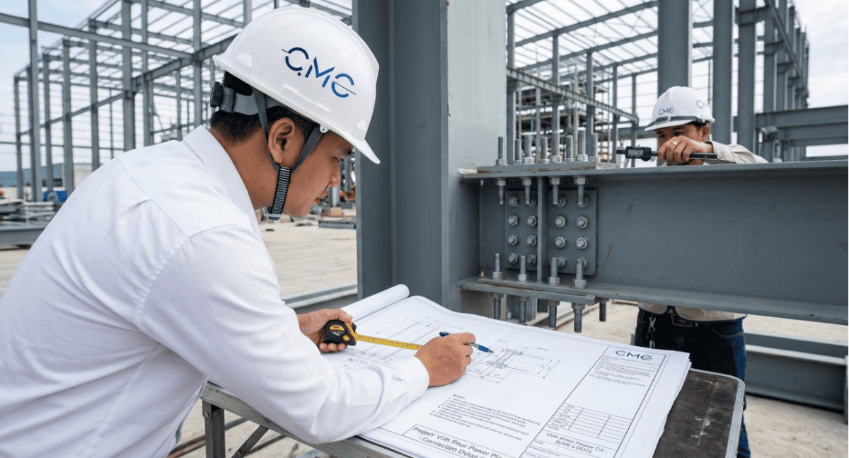
Steelwork is often directly related to the structure and sometimes to MEP (Mechanical, Electrical, and Plumbing). Therefore, after reviewing the architectural drawings, it's necessary to check the relevant drawings as well.
See also:
Load-bearing columns, beams, slabs, and walls.
Location of reinforcing steel or anchor drilling areas.
Floor, wall, or ceiling finishes.
Air ducts, cable trays, and technical piping.
Technical equipment near the installation area.
Work, maintenance, and operation space.
Areas requiring waterproofing, fire protection, or corrosion protection.
For example, when drawing a technical access ladder, it's necessary to check if the ladder will obstruct pipes, cable trays, or operating equipment. When drawing a steel door frame for a technical area, it's necessary to check if the door opening direction will obstruct MEP equipment.
Architectural information helps determine location, but structural and MEP information helps check the feasibility of actual construction.
7. Determine which information can be used immediately and which information needs verification
After reading the architectural drawings, don't immediately include all the information in the drawing. It's necessary to clearly categorize them into three groups:
Group 1: Information that can be used immediately
This information is clear, agreed upon, and ready to be used for drawing implementation, for example, item location, finalized overall dimensions, clear elevations, or confirmed materials.
Group 2: Information requiring verification
This information may be correct but requires further verification, for example, opening dimensions, finished elevation, wall position after construction, actual site dimensions, or information between drawings that may not be entirely consistent.
Group 3: Missing information that needs clarification
This information is not yet included in the architectural drawings but is necessary for the development of technical drawings, such as base plate dimensions, bolt types, welding methods, installation tolerances, surface finish requirements, or handover standards.
This classification helps the design team avoid confusing "confirmed information" with "information requiring confirmation." This is a crucial step in reducing errors during AutoCAD 2D development
8. Create a checklist before drawing steel components in AutoCAD 2D
Before starting to draw in AutoCAD 2D, you should create a checklist of input information. This checklist helps control the data and ensures that no important elements are missed.
The checklist should include:
Item Name (to be implemented):
Installation Location:
Relevant Architectural Drawings:
Relevant Structural Drawings:
Relevant MEP Drawings (if any):
Overall Dimensions:
Dimensions to be checked in person:
Relevant Elevations:
Materials Used:
Surface Finish:
Connection Method:
Safety Requirements:
Aesthetic Requirements:
Scope of Drawings to be Delivered:
File Format: To be Delivered:
Regarding any Missing Points Requiring Reconciliation.
A clear checklist helps to make the 2D AutoCAD drawing process more focused, avoiding the need to stop drawing repeatedly to find information or ask for clarification.
11. Deploy AutoCAD 2D after classifying the information.
Once the information has been read and clearly categorized, the implementation of AutoCAD 2D will be much more efficient.
AutoCAD 2D can be used to represent:
Steelwork layout plan.
Elevation.
Section.
Enlarged details.
Base plate details.
Bolt details.
Weld details.
Details of connections to floor, wall, beam, or panel.
Component dimensions.
Installation elevation.
Material notes.
Finishing notes.
Component quantity table.
It is crucial that AutoCAD 2D drawings not only "recreate" information from architectural drawings, but also develop into engineering drawings that can be used for fabrication, installation, and quality control.
This is the value of engineering drawings in steel projects.
9. The role of BIM in checking information before drawing details
Besides AutoCAD 2D, BIM can support overall review before detailed drawing implementation.
BIM helps to check:
Position of steel elements in 3D space.
Collisions with other structures, MEP, or architectural elements.
Installation elevation and clearance.
Relationship between stairs, railings, panels, louvers, door frames, and technical systems.
Feasibility of construction.
Areas requiring adjustments before drawing release.
BIM doesn't replace 2D AutoCAD drawings, but it gives the engineering team a more comprehensive overview. When BIM and 2D AutoCAD are combined effectively, the steel reinforcement drawings will be both detailed and provide better overall project control.
10. Common mistakes when not carefully reading architectural drawings.
When architectural drawings are not read carefully or information is not properly categorized, many errors can occur during the AutoCAD 2D implementation process.
Some common errors include:
Using incorrect dimensions from architectural drawings.
Failing to check finished elevations.
Omitting important cross-sections.
Failing to compare floor plans with elevations.
Failing to check the position of columns, beams, walls, or panels.
Missing connection details in drawings.
Failing to clarify finishing materials.
Failing to check for conflicts with MEP (Mechanical, Electrical, and Plumbing) systems.
Using outdated, unupdated information from drawings.
Failing to note points requiring confirmation before releasing the drawings.
11. How does CMC Architects Vietnam support the implementation of AutoCAD 2D for steel structures

At CMC Architects Vietnam, we understand that a quality 2D AutoCAD drawing doesn't start with the drawing process itself, but with correctly reading, understanding, and classifying the input information.
During the steel structure drawing development process, CMC Architects Vietnam focuses on:
Receive and review architectural drawings.
Classify information by location, dimensions, elevation, materials, and connections.
Compare architectural drawings with structural, MEP, and real-world conditions.
Identify points requiring confirmation before implementation.
Develop clear and readable 2D AutoCAD drawings.
Apply BIM for overall verification when needed.
Control details of base plates, bolts, welds, and connections.
Review consistency between views before handover.
CMC Architects Vietnam provides support for various projects, including:
Steel railings.
Handrails.
Steel staircases.
Technical ladders.
Steel door frames.
Louvers.
Panels.
Secondary steel frames.
Base plates, bolts, and connecting details.
Other architectural metal items.
Our goal is to create clear, accurate, easy-to-manufacture, and easy-to-implement technical drawings, helping clients reduce errors and improve project implementation efficiency.
12. Conclusion
Before creating 2D AutoCAD drawings of steel structures, reading and classifying information from architectural drawings is an indispensable step. This is the foundation that helps the engineering team correctly understand the location, dimensions, elevations, materials, connections, and related conditions of the item to be implemented.
A good 2D AutoCAD drawing comes not only from software skills but also from the ability to accurately analyze input information.
Before starting to implement steel structure drawings, ask yourself:
Is the item to be drawn clearly defined?
Has the installation location been checked on the plan, elevation, and section?
Have the dimensions and elevations been clearly classified?
Have the materials and surface finishes been confirmed?
Is there enough information for detailed implementation of the connection plan?
Have the architectural, structural, and MEP drawings been reconciled?
If this information is fully prepared, the AutoCAD 2D drawing process will be more accurate, faster, and more efficient.
If you need assistance with reading architectural drawings, classifying input information, implementing AutoCAD 2D, BIM, and shop drawings for architectural steel and metal elements, please contact CMC Architects Vietnam for consultation and support in your project.
CMC Architects Vietnam – Partnering with you from architectural drawings to clear, accurate, and professional AutoCAD 2D steel element drawings.