Why do steel structure drawings need to be so accurate?
If the blueprints don't answer these questions, the project is very likely to encounter difficulties during the actual implementation phase
Error 1: Missing dimensions and important technical information
For example, in steel railing drawings, if the spacing between the vertical posts is missing, the manufacturing workshop may have to guess. In steel staircase drawings, if the step height or the length of the connecting plates is missing, fabrication may be inaccurate. With louvers or panels, if the modules, frame spacing, or fixed positions are not clearly shown, installation problems are very likely to arise.
A professional technical drawing should clearly show:
- Overall dimensions of the item.
- Dimensions of each main component.
- Dimensions of base plates, boreholes, bolts, and welds.
- Installation elevation and connection location.
- Material specifications, thickness, and cross-section.
- Technical notes for production and construction.
- Plan, elevation, section, and enlarged details as needed.
How to minimize size errors
Error 2: Drawings are inconsistent between floor plans, elevations, sections, and details
Another "fatal" error is the inconsistency between different parts of the drawing set.
- The dimensions between the plan view and the elevation view are inconsistent.
- The elevation between the section view and the overall drawing is mismatched.
- The number of bolts in the views is inconsistent.
- The material symbols are inconsistent.
- The component codes are duplicated or incorrect.
- The enlarged details do not match the overall drawing.
- Old and new versions of the drawing are being used interchangeably.
In particular, when a drawing is revised multiple times, the risk of discrepancies between drawings increases significantly if version control is not properly implemented.
Why are synchronization errors so common?
Because steel structures are often highly interconnected, a small change in one location can affect the entire system.
For example, changing the railing height will affect the length of the uprights, the position of the handrail, the base plates, and the installation height. Changing the stair slope will affect the number of steps, step size, the length of the end beams, and the connection points. Changing the louver module can affect the support frame, bolt placement, and the aesthetics of the facade.
If the drawings are not updated consistently, errors will spread from the drawings to the workshop and the construction site.
How to minimize asynchronous errors
Before releasing the drawings, cross-checking between parts is necessary:
- Floor plan versus elevation.
- Elevation versus section.
- Section versus magnified detail.
- Materials list versus drawing.
- Component code in drawing versus catalog.
- AutoCAD 2D drawing versus BIM model, if available.
Furthermore, clear drawing version control is essential. Each revision should include a revision code, update date, and details of the changes. This helps all parties know which drawing is the most up-to-date version to use.
A consistent set of drawings not only reduces errors but also fosters professionalism and trust in project collaboration.
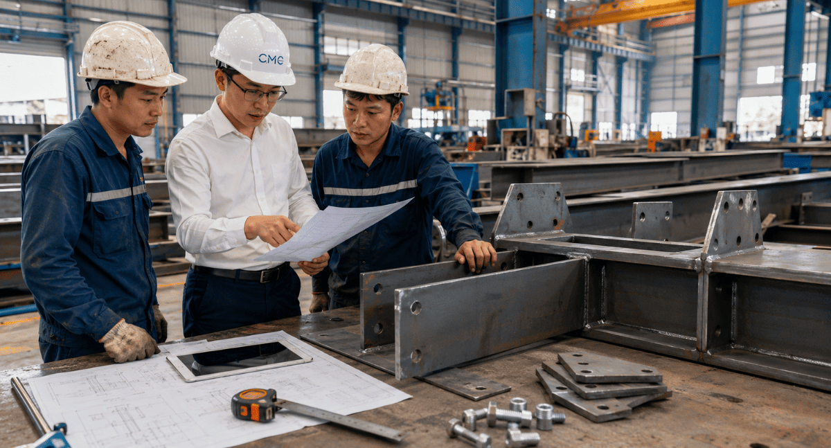
Error 3: Failure to consider actual production and construction capabilities
This is a very easy mistake to overlook. A drawing may be geometrically correct, but it's not necessarily suitable for manufacturing and construction.
In reality, workshops and construction teams always face many specific conditions: available material dimensions, cutting, welding, drilling, and bending capabilities, transportation limitations, installation space, lifting conditions, operating locations, construction sequence, and future maintenance possibilities.
If the person implementing the drawing focuses only on the shape without considering the construction feasibility, the drawing may be difficult to implement in practice.
Some common examples:
- The steel modules are too large, making them difficult to transport or lift and install.
- The bolt positions are too close to the edges, making installation difficult or technically flawed.
- Welded details are located in hard-to-reach positions.
- The base plate does not have enough space for bolt tightening.
- The louvers or panels are not divided into modules properly.
- The steel staircase does not take into account the installation sequence.
- The steel railing is unsuitable for the existing ground conditions or structure.
- The design details are aesthetically pleasing but difficult to maintain after completion.
These problems often only become apparent when the factory begins production or the construction site is preparing for installation. At that point, corrections will take more time than if they were checked during the design phase
Ways to minimize unrealistic errors
To ensure the practicality of steel structure drawings, the implementer needs to consider all three perspectives:
Design perspective: the elements must be aesthetically pleasing, align with the design concept, and fit the overall architecture.
Manufacturing perspective: the components must have clear machinability, appropriate materials, and feasible details.
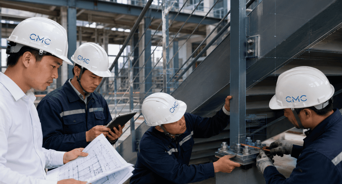
Construction perspective: the elements must be transportable, installable, operable, and verifiable on-site.
For elements such as railings, steel staircases, louvers, panels, ladders, or steel frames, the drawings should clearly show the module division plan, connection locations, installation directions, and other important details for construction.
If the project involves multiple overlapping technical systems, combining AutoCAD 2D and BIM can also help detect conflicts early, minimizing the need for on-site troubleshooting.
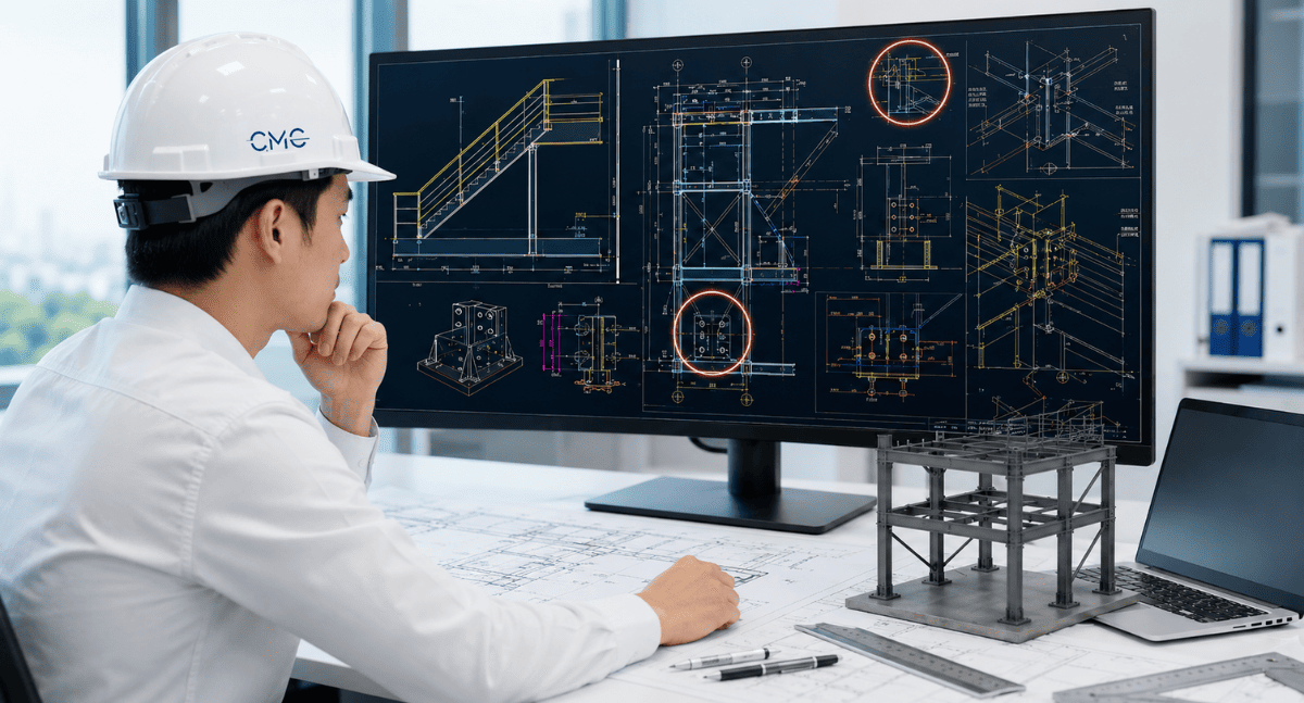
The role of AutoCAD 2D and BIM in controlling errors in steel drawing
AutoCAD 2D remains a crucial tool for developing detailed drawings, shop drawings, and technical documentation for steel structures. With AutoCAD 2D, engineers can clearly represent floor plans, elevations, sections, dimensions, notes, and connection details.
Meanwhile, BIM provides better overall inspection capabilities. BIM models help stakeholders visualize space, check for conflicts, coordinate between systems, and detect problems before construction.
When AutoCAD 2D and BIM are combined effectively, steel structure drawings offer numerous advantages:
- Clearly shows details.
- Better dimensional control.
- Early detection of conflicts.
- Minimizes discrepancies between design and construction.
- Helps the manufacturing plant understand requirements correctly.
- Facilitates smoother implementation by the construction team.
This is also why modern projects increasingly focus on the coordination process between 2D drawings, BIM models, the manufacturing plant, and the construction site
How can we make steel structure drawings more professional?
A professional steel structure drawing is not just about accurately depicting the shape. More importantly, the drawing must be easy to read, easy to inspect, easy to manufacture, and easy to construct.
To improve the quality of drawings, the following should be noted:
- Standardize AutoCAD layers.
- Control dimensions and technical notes.
- Show full detail of connections.
- Use cross-sections and zoomed-in details at critical locations.
- Check consistency between drawings.
- Control drawing versions.
- Compare with site conditions.
- Coordinate with the production workshop before fabrication.
- Apply BIM when conflict checking or coordination of multiple systems is required.
The clearer the drawings, the less risk there is during construction. The better the drawings are controlled, the easier it is to limit unexpected costs
CMC Architects Vietnam provides professional steel structure drawing implementation support
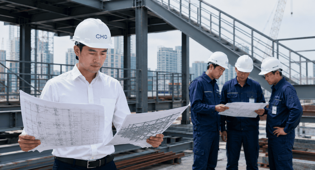
At CMC Architects Vietnam, we understand that every technical drawing directly impacts the production, construction, and final quality of a project.
With experience in technical drawing implementation, AutoCAD 2D, BIM, shop drawings, and architectural steel and metalwork, CMC Architects Vietnam supports clients in developing drawing documentation for various projects such as:
- Steel railings.
- Handrails.
- Steel staircases.
- Ladders.
- Louvers.
- Panels.
- Steel frames.
- Base plates.
- Connecting bolts.
- Other architectural metal components.
We prioritize clarity, accuracy, and practical applicability of the drawings. Our goal is to help the manufacturing plant understand the drawings correctly, facilitate installation by the construction team, and minimize project errors
Conclude
Steel structure drawings are a crucial foundation for connecting design ideas with actual production and construction. If the drawings lack dimensions, are inconsistent, or fail to account for feasibility, the project is very likely to encounter difficulties during implementation.
Three critical errors to avoid include:
Missing dimensions and important technical information.
Inconsistent drawings across floor plans, elevations, sections, and details.
Failure to consider actual production and construction feasibility.
If you are preparing to implement steel structure work for a project, try checking the following:
Are the current drawings clear enough for the fabrication workshop to understand correctly?
Are the details of plates, bolts, welds, and connections fully shown?
Is the set of drawings consistent across floor plans, elevations, sections, and details?
Does the drawing plan take into account actual production, transportation, and installation?
If the answer is no, now is the right time to review and upgrade the quality of your drawings.
Contact CMC Architects Vietnam today for advice on technical drawing implementation solutions, AutoCAD 2D and BIM for steel structures, helping your project be more accurate, professional, and efficient from drawing to actual construction.
- 📞 Hotline: 0936361299
- 📧 Email: cmc.vn1013@gmail.com
- 🌐 Website: https://cmcarchitects.com/
- 📍 Address: 79A Xuan La, Tay Ho, Hanoi


