A good set of drawings will help the manufacturing workshop understand the correct dimensions, materials, connection details, and fabrication methods. At the same time, it will make it easier for the construction team to install the door frame in the correct position, minimizing errors and reducing problems on the construction site.
So what does a steel door frame drawing include? What factors need to be checked during the design process? And how are steel door frames used in practice? Let's explore the details with CMC Architects Vietnam in the article below.
What is a steel door frame drawing?

Steel door frame drawings are technical documents that fully detail the shape, dimensions, materials, structure, and installation plan of a steel or metal door frame system.
These drawings are commonly used in the engineering design phase, shop drawings, factory production, and on-site installation. Depending on project requirements, the drawings can be created using AutoCAD 2D, combined with BIM modeling or other relevant technical documents.
A professional steel door frame drawing typically includes:
-Floor plan showing the door frame location.
- Elevation view of the door frame.
- Detailed cross-section.
- Overall dimensions.
- Frame profile dimensions.
- Steel material specifications.
- Details of base plates, bolts, screws, welds, or anchors.
- Installation location on the wall, steel frame, panel, or main structure.
- Notes on surface finish such as painting, galvanizing, or anti-corrosion treatment.
- Manufacturing and installation tolerances, if required.
- Table summarizing the quantity, model number, and type of door frames.
Simply put, steel door frame drawings are a "common language" that helps designers, manufacturers, and construction teams understand the same information correctly.
Why are steel door frame drawings important?
Steel door frames may seem like a simple item, but in reality, they involve many factors: opening size, wall flatness, type of door used, opening direction, hinge position, lock, accessories, installation gaps, connection to the structure, and surface finish requirements.
If the drawings are unclear, problems such as:
- The door frame does not match the actual opening.
- Incorrect width or height dimensions.
- The hinges, locks, or accessories are misaligned.
- The steel frame is warped due to improper construction.
- The connection to the wall or structure is not secure.
- The paint, plating, or surface finish does not meet requirements.
- Additional cutting, drilling, or fabrication is required on-site.
- This delays the door installation and project completion.
For steel structures or factory buildings, small deviations in the door frame can affect panels, louvers, curtain walls, industrial door systems, technical systems, and even the aesthetics of the facade.
Therefore, steel door frame drawings need to be carefully controlled from the outset, rather than only being addressed when issues arise on site.
Essential information to include in a steel door frame drawing

1. Overall dimensions of the door frame
Overall dimensions are fundamental but crucial information in steel door frame drawings. These dimensions typically include width, height, frame thickness, and installation position relative to the finished floor level.
When checking overall dimensions, it's important to clarify:
- Opening size (building cutout).
- Overall dimensions of the door frame.
- Clearance dimensions after installation.
- Base height of the frame relative to the finished floor.
- Installation clearance between the frame and the wall or structure.
- Compatibility with the type of door leaf, accessories, and intended use.
If the overall dimensions are incorrect, the entire manufacturing and installation process can be affected. This is a common but preventable error if the drawings are thoroughly checked before delivery
2. Specifications for steel materials and cross-sections
Steel door frames can be made from various materials such as square steel tubing, folded sheet steel, galvanized steel, powder-coated steel, stainless steel, or other types of steel with surface treatments suitable for the application environment.
The drawing must clearly show:
- Material type.
- Cross-sectional dimensions.
- Material thickness.
- Steel grade or technical requirements, if applicable.
- Surface finish option.
- Requirements for rust, corrosion, or fire resistance, if required by the project.
Specifying the materials helps the manufacturer select the correct type, avoids errors during processing, and ensures the door frame meets the required quality standards
3. Floor plans, elevations, and detailed sections
A steel door frame drawing shouldn't just include an overall elevation. For proper understanding by the workshop and construction team, the drawing needs to include detailed floor plans, elevations, and cross-sections.
Floor plans help determine the frame's position in space, the door's opening direction, and its relationship to walls, columns, partitions, or panel systems.
Elevations show the height, width, frame layout, hinges, locks, accessories, and details visible from the front.
Cross-sections clarify the internal structure, frame thickness, wall connections, installation gaps, and surrounding finishes.
For complex areas, enlarged details should be added to better show the base plates, bolts, anchors, welds, or finishing gaskets.
4. Details of connections to walls, steel frames, or panels
Steel door frames typically do not stand alone. They need to be attached to masonry walls, concrete, steel structures, panel walls, louvers, or other cladding elements.
Therefore, the details of the connection are a very important part of the drawing.
Need to check:
- What type of substrate material is the door frame attached to?
- Are bolts, screws, plates, welding, or anchors used?
- What is the spacing between the connection points?
- Is there sufficient space for construction at the connection point?
- Are there any obstructions from MEP systems, panels, auxiliary structures, or finishing layers?
- Are expansion joints or waterproofing/vibration damping treatments required?
If the connection details are unclear, the construction team may have to handle them themselves on-site. This can easily lead to technical errors, reduced structural integrity, and affect the finished aesthetics.
5. Location of hinges, locks, and accessories
For steel door frames, the location of hinges, locks, latches, handles, gaskets, sliding rails, or other accompanying accessories must be clearly shown in the drawings
The required information includes:
- Number of hinges.
- Hinge position according to height.
- Load and handle position.
- Size of cutouts or fittings.
- Door opening direction.
- Gap between door leaf and frame.
- Reinforcement details at load-bearing points.
If the hinges or locks are misaligned, installing the door can be difficult. In some cases, the workshop may have to rework the components or the construction site may have to perform additional drilling and cutting, wasting time and affecting the surface finish
6. Manufacturing and installation tolerances
Steel door frames need to be manufactured precisely, but actual on-site tolerances must also be taken into account. Existing openings, walls, floors, or steel frames may have slight deviations from the design drawings.
Therefore, the drawings should show or note any issues related to tolerances:
- Frame dimensional tolerances.
- Connection hole position tolerances.
- Installation clearance.
- Locations requiring actual measurements before mass production.
-Solutions for minor deviations in the opening.
- Post-machining inspection requirements.
Well-controlled tolerances will make door frame installation easier, reduce the risk of on-site repairs, and maintain overall accuracy
Applications of steel door frames in construction
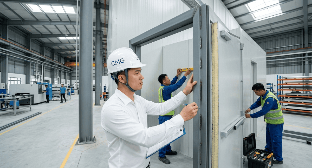
1. Steel door frames in factories and industrial buildings
In industrial settings, steel door frames are commonly used for technical doors, emergency exits, warehouse doors, production area doors, machine room doors, or other locations requiring high durability.
Steel door frames are suitable for industrial environments because they have good load-bearing capacity, are easy to fabricate, easily connect to steel structures, and can be surface-treated to increase rust resistance.
For factories using panel systems, steel door frames need to be carefully coordinated with the wall system, panel edges, sub-frames, and installation location to ensure a tight, secure, and aesthetically pleasing fit
2. Steel door frames in townhouses and civil constructions
In townhouses or residential buildings, steel door frames can be used for main entrances, side entrances, technical area doors, terrace doors, basement doors, or other areas requiring robustness.
If well-designed, steel door frames are not only durable but can also create a modern, minimalist feel and suit many architectural styles.
For modern townhouses, steel door frames often need to be coordinated with glass, wood, louvers, railings, steel staircases, or other architectural metal details to create overall harmony.
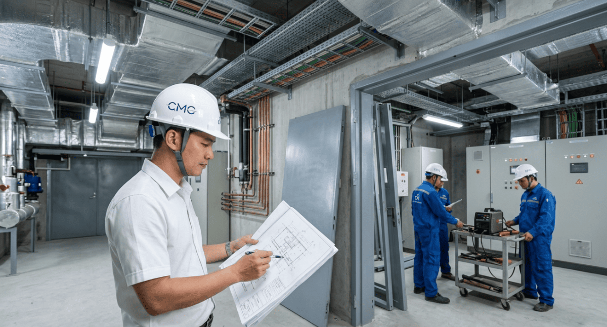
3. Steel door frames in the technical area and MEP system
In technical areas, steel door frames are commonly used for doors to electrical rooms, machine rooms, operation areas, maintenance areas, or spaces requiring high security.
In these locations, the drawings should also consider:
- Clear opening dimensions for equipment installation.
- Convenient door opening direction for operation.
- Frame durability.
- Rust, fire, or impact resistance if required.
- Coordination with surrounding MEP systems.
A clear drawing will help make the installation of the door frame in the technical area smoother and safer
The role of AutoCAD 2D in steel door frame drawings
AutoCAD 2D is a very suitable tool for creating steel door frame drawings because it can clearly display necessary technical information such as floor plans, elevations, sections, dimensions, connection details, material notes, and schedules.
With AutoCAD 2D, engineers can control:
- Door frame dimensions.
- Details of each steel bar.
- Location of hinges, locks, and accessories.
- Details of base plates, bolts, anchor screws, or welds.
- Installation clearance.
- Frame height and position within the building.
- Quantity and part number summary table.
A clear set of 2D AutoCAD drawings helps the manufacturing workshop avoid misunderstandings and ensures the installation team installs correctly according to the technical specifications
The role of BIM in coordinating steel door frames
For projects with multiple technical elements, BIM helps to check the steel door frame within the overall building space. Instead of just looking at each individual cross-section, the BIM model allows parties to check the position of the door frame in relation to walls, panels, steel structures, MEP systems, louvers, stairs, or other related details.
BIM support:
- Check for collisions with the technical system.
- Check the door opening space.
- Check the height and installation location.
- Coordinate the door frame with the panels, walls, and structure.
- Reduce discrepancies between the drawings and actual construction.
- Help the investor, manufacturer, and construction team visualize the project more easily.
When combining AutoCAD 2D and BIM, steel door frame drawings are not only more detailed but also more accurate in terms of the overall structure
Common mistakes in steel door frame drawings
Some common errors include:
- Overall dimensions are missing.
- Clear opening dimensions are not shown.
- Detailed cross-sections are missing.
- Steel material and thickness are not specified.
- Surface finish information is missing.
- Hinge, lock, or accessory placement is unclear.
- Connection details to walls or steel frames are too rudimentary.
- Installation tolerances are not checked.
- Coordination with surrounding panels, MEP, or structures is lacking. Drawings are inconsistent across views.
These errors can cause the manufacturing plant to require multiple follow-up requests, slowing down the processing schedule and creating difficulties during installation
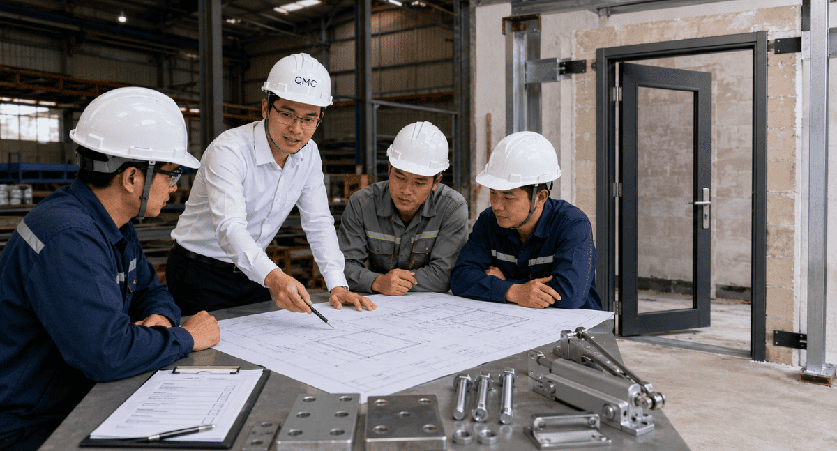
CMC Architects Vietnam provides professional steel door frame design support
At CMC Architects Vietnam, we understand that a good set of steel door frame drawings needs to be both technically clear and suitable for practical production and installation.
With experience in technical drawing design, AutoCAD 2D, BIM, shop drawing, and architectural steel and metal projects, CMC Architects Vietnam supports the development of drawings for many projects such as:
- Steel door frames.
- Steel staircases.
-Steel railings.
- Handrails.
- Technical ladders.
- Louvers.
- Panels.
- Architectural steel frames.
- Boards, bolts, and connecting details.
- Other architectural metal details.
We prioritize checking dimensions, materials, connection details, constructability, consistency of drawings, and actual site conditions before handover.
Our goal is to provide clients with a set of drawings that are easy to read, easy to manufacture, easy to install, and minimize risks during construction.
Conclude
Steel door frame drawings are crucial documents connecting design ideas with actual production and construction. Clear drawings ensure accurate fabrication, smooth installation, and guarantee durability, safety, and aesthetics for the project.
When developing steel door frame drawings, the following should be carefully checked:
Overall dimensions.
Clear opening dimensions.
Material specifications.
Floor plans, elevations, and detailed cross-sections.
Details of connections to walls, steel frames, or panels.
Location of hinges, locks, and accessories.
Manufacturing and installation tolerances.
Coordination with AutoCAD 2D, BIM, and related engineering systems.
If you are preparing to install steel door frames for your project, ask yourself:
Are the current drawings clear enough for the fabrication workshop to understand correctly?
Are the connection details suitable for actual construction conditions?
Has the door frame been checked for consistency with the panels, structure, MEP, and surrounding elements?
If the answer is no, now is the right time to review the drawings before production begins.
Contact CMC Architects Vietnam today for support in developing technical drawings, AutoCAD 2D, and BIM for steel door frames, ensuring your project is more accurate, professional, and efficient from drawing to actual construction.
- 📞 Hotline: 0936361299
- 📧 Email: cmc.vn1013@gmail.com
- 🌐 Website: https://cmcarchitects.com/
- 📍 Address: 79A Xuan La, Tay Ho, Hanoi


