In construction projects, especially those with high technical requirements like Japanese projects, drawings are not just documents to look at. They are the basis for manufacturing, fabrication, installation, quality control, and coordination among various stakeholders.
For steel components such as steel railings, handrails, steel staircases, technical ladders, steel door frames, louvers, panels, base plates, bolts, and connecting details, even a single unclear piece of information can lead to misunderstandings by the manufacturing plant, incorrect installation by the construction team, or additional time spent on revisions.
For Japanese projects, the demands for accuracy, discipline, and information control are typically very high. Therefore, steel component drawings for Japanese projects need to be clear, consistent, and easy to understand from the outset.
So, what criteria define a clear set of steel component drawings? Let's explore the details with CMC Architects Vietnam in the article below.
1. Why is clarity necessary in steel reinforcement drawings for Japanese construction projects
Japanese construction projects often prioritize precision in every detail. Every dimension, symbol, note, material, or connection method needs to be clearly shown so that all parties can work together in harmony.
An unclear drawing can lead to many problems, such as:
- The factory misunderstood the component dimensions.
- The construction team couldn't determine the correct installation location.
- Details for base plates, bolts, or welds were missing.
- Plans, elevations, and sections didn't match.
- Technical questions had to be resubmitted multiple times.
- Time was wasted checking, correcting, and updating documentation.
- Increased risk of cost overruns at the factory or construction site.
In steel construction, many components are prefabricated in the factory before being brought to the construction site for installation. Therefore, if the drawings are unclear from the outset, errors can persist through many subsequent steps.
In other words, the clearer the drawings, the smoother the production and construction process.
2. Clear overall dimensions and detailed dimensions
The first factor to control in steel fabrication drawings is dimensions.
A good drawing should not only show the overall dimensions but also clearly detail the dimensions of each small part. For items such as steel staircases, railings, steel door frames, or louvers, each dimension directly affects the fabrication and installation process.
The drawing needs to clearly show:
- Overall length, width, and height.
- Dimensions of individual steel bars, columns, and frames.
- Spacing between components.
- Installation elevation.
- Clearance dimensions, if applicable.
- Installation clearance.
- Dimensions of base plates, bolt holes, and anchor points.
- Manufacturing and installation tolerances, if required by the project.
For example, with steel railing drawings, if the spacing of the railing posts or the height of the handrail are not clearly shown, the construction team may install it incorrectly compared to the design requirements. With steel door frames, if the dimensions of the opening, the overall dimensions, and the installation clearance are unclear, the door frame may not match the actual construction.
Therefore, dimensions in drawings need to be presented fully, clearly, and avoid misunderstandings.
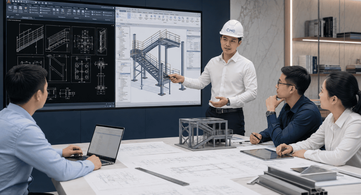
3. Clear floor plans, elevations, and sections
A steel structure drawing shouldn't just show the overall layout. For the fabrication workshop and construction team to understand correctly, the drawing needs to include floor plans, elevations, sections, and zoomed-in details when necessary.
Each type of drawing has a specific role:
Floor plans help determine the location of the item in space and its relationship to surrounding walls, floors, columns, panels, or structures.
Elevations clearly show the overall shape, height, steel bar layout, handrail locations, hinges, frames, louvers, or details visible from the front.
Sections clarify the internal structure, material thickness, connection methods, finishes, and installation clearances.
Zoomed-in details show complex areas such as base plates, bolts, welds, anchor bolts, connections to walls, connections to steel frames, or intersections between multiple components.
Especially in Japanese construction projects, presenting all views helps minimize the need for repeated questioning. When a reader can understand the technical intent simply by looking at the drawing, that's a sign of a high-quality drawing file.
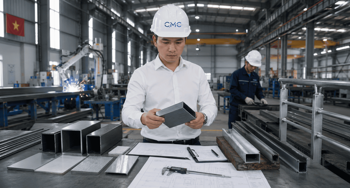
4. Clarity regarding steel material and specifications
Material information is essential in steel fabrication drawings. If the drawing only shows the shape without specifying the material, the factory will have difficulty selecting the correct type of steel and fabrication method.
The drawing needs to clearly show:
- Type of steel used.
- Cross-sectional dimensions.
- Material thickness.
- Steel grade or technical requirements, if applicable.
- Surface finish option.
- Painting, galvanizing, powder coating, or anti-corrosion treatment.
- Corrosion resistance, fire resistance, or impact resistance requirements, if required by the project.
For outdoor items such as railings, louvers, ladders, or supporting steel frames, the materials and surface treatments need to be clearly specified. This ensures better durability of the finished product, suitability for the environment, and long-term aesthetic appeal.
A clear drawing of the materials reduces the risk of errors during production and avoids the need for changes after fabrication.
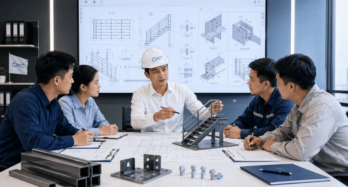
5. Clear details of connections, plates, bolts, and welds
For steel structures, the details of the connections are extremely important. No matter how aesthetically pleasing a component is, if the connections are unclear, the installation process can still be difficult.
The drawings need to clarify:
- Base plate location.
- Base plate dimensions.
- Base plate thickness.
- Number and diameter of bolts.
- Bolt hole spacing.
- Type of anchor bolt or screw.
- Weld location.
- Length, marking, and welding requirements, if any.
- Connection method to wall, floor, column, steel frame, or panel.
- Actual working space during installation.
In Japanese construction, connection details need to be clearly, logically, and easily verifiable. If unclear, the construction team may have to handle things themselves on-site. This can easily lead to technical errors, reduced quality of finish, and delays.
A good set of drawings should help the contractor answer the question: “Where does this detail fit, what is it made of, what are its dimensions, and how should it be installed?”
6. Clarity of technical notes and drawing symbols
Technical notes are often overlooked, but they play a crucial role in drawing documentation.
A clear steel structure drawing requires a well-defined, consistent, and unambiguous system of notes. Symbols, lines, hatches, layers, component codes, and annotations must be presented uniformly throughout the entire document.
Elements such as:
- Component symbols.
- Material symbols.
- Weld, bolt, and plate symbols.
- Surface finish notes.
- Pre-production inspection notes.
- Tolerance notes.
- Notes on areas requiring coordination with other disciplines.
- Notes on version changes or updates.
If the symbols are inconsistent, the reader of the drawing will waste time trying to understand it. If the notes are unclear, each party may interpret them differently. This is especially unsuitable for projects requiring high accuracy.
Therefore, technical notes need to be concise, to the point, and consistent
7. Clear consistency between drawings
A common error during the document implementation process is that the drawings are not synchronized with each other.
For example:
- The floor plan shows one dimension, but the elevations show a different dimension.
- The cross-sections have not been updated to reflect the new design.
- The enlarged details do not match the overall drawing.
- The material list has not been updated to reflect the latest drawings.
- The BIM model has changed, but the AutoCAD 2D drawings still use the old data.
For Japanese construction projects, consistency between drawings is crucial. Documentation must be thoroughly checked before handover to avoid discrepancies between parties using different sources of information.
A professional set of drawings should ensure:
- Floor plans, elevations, and sections match.
- Dimensions are consistent throughout the entire documentation.
- Component codes are not duplicated or missing.
- The schedule matches the drawings.
- The drawing version is clearly controlled.
- Changes are updated synchronously.
Clarity lies not only in each individual drawing, but also in the consistency of the entire set of documents
8. Clarity regarding version and edit history.
During a project, drawings often need to be updated multiple times based on feedback from clients, architects, structural engineers, the manufacturer, or the construction site.
Without version control, the following situations can easily occur:
- The workshop used outdated blueprints.
- The construction team received the wrong version.
- Some details were modified but not fully updated.
- It's unclear which changes are the latest.
- Time is wasted checking the revision history.
Therefore, steel reinforcement drawings for Japanese construction projects need clear version information. Each update should be fully documented with the revision date, changes made, and the scope of impact.
This helps all parties track progress easily, reduces confusion, and promotes a more professional workflow.
9. The role of AutoCAD 2D in steel structure drawings
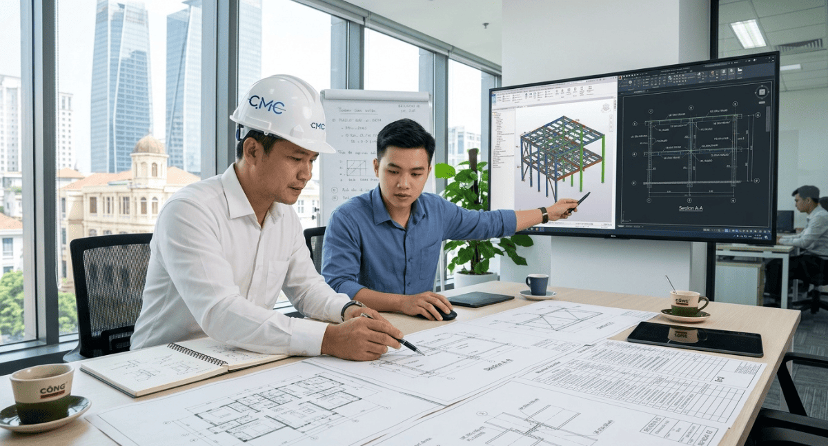
AutoCAD 2D remains a very important tool in the development of steel structure drawings. With AutoCAD, engineers can show every detail, dimension, annotation, cross-section, and technical connection.
AutoCAD 2D is particularly effective in the following areas:
- Fabrication drawings.
- Installation drawings.
- Base plate details.
- Bolt details.
- Weld details.
- Floor plans, elevations, and sections.
- Component quantity list.
- Technical handover documents.
For Japanese projects, AutoCAD drawings need to be presented cleanly, with clear layers, consistent symbols, and easy to check. This is the foundation for smoother coordination between design, production, and construction
10. The role of BIM in steel item inspection and coordination
In addition to AutoCAD 2D, BIM helps in the overall inspection of steel components within a construction project.
BIM supports:
Check for collisions between steel elements and the structure.
Coordinate with the MEP system.
Check installation positions in 3D space.
Determine the relationship between railings, stairs, panels, louvers, door frames, and surrounding elements.
Assist in visualizing the design before construction.
Reduce discrepancies between drawings and reality.
When AutoCAD 2D and BIM are properly combined, the drawing documentation will be both highly detailed and easy to manage overall. This approach is very suitable for projects with high demands for quality and accuracy.
11. CMC Architects Vietnam assists in the implementation of steel structure drawings for a Japanese project
At CMC Architects Vietnam, we understand that steel reinforcement drawings for Japanese construction projects require more than just aesthetics. The key is that the drawings must be clear, accurate, easy to understand, consistent, and suitable for actual construction.
CMC Architects Vietnam supports the development of technical drawings for various projects, including:
Steel railings.
Handrails.
Steel staircases.
Technical ladders.
Steel door frames.
Louvers.
Panels.
Secondary steel frames.
Base plates, bolts, and connecting details.
Other architectural metal items.
During the implementation process, we focused on:
Verify input information.
Create clear 2D AutoCAD drawings.
Use BIM to support overall inspection if required by the project.
Control dimensions, elevations, and materials.
Check connection details.
Ensure consistency between views.
Review the version before handover.
Aim for documents that are easy to read, easy to produce, and easy to construct.
CMC Architects Vietnam's goal is to help clients obtain a professional set of architectural drawings, minimize errors, and support more efficient project operation from the design phase to the actual construction phase.
12. Conclusion
Steelwork drawings for Japanese construction projects require clarity on multiple levels: clarity of dimensions, materials, structure, connections, annotations, versions, and consistency throughout the entire documentation.
A clear drawing not only helps the fabrication workshop work correctly, but also enables the installation team to install accurately, facilitates client inspection, minimizes project issues, and enhances professionalism throughout the entire process.
Have you ever encountered a situation where a drawing lacked information, causing delays in fabrication or installation?
Does your project need a clearer, more readable, and more technically compliant set of steelwork drawings?
If you are looking for a company to assist with the implementation of AutoCAD 2D, BIM, and shop drawings for architectural steelwork, contact CMC Architects Vietnam for consultation and support on your project.
CMC Architects Vietnam – Partnering with you in every technical drawing, ensuring clarity, accuracy, and professionalism.


