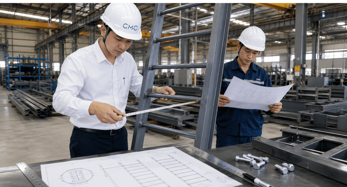
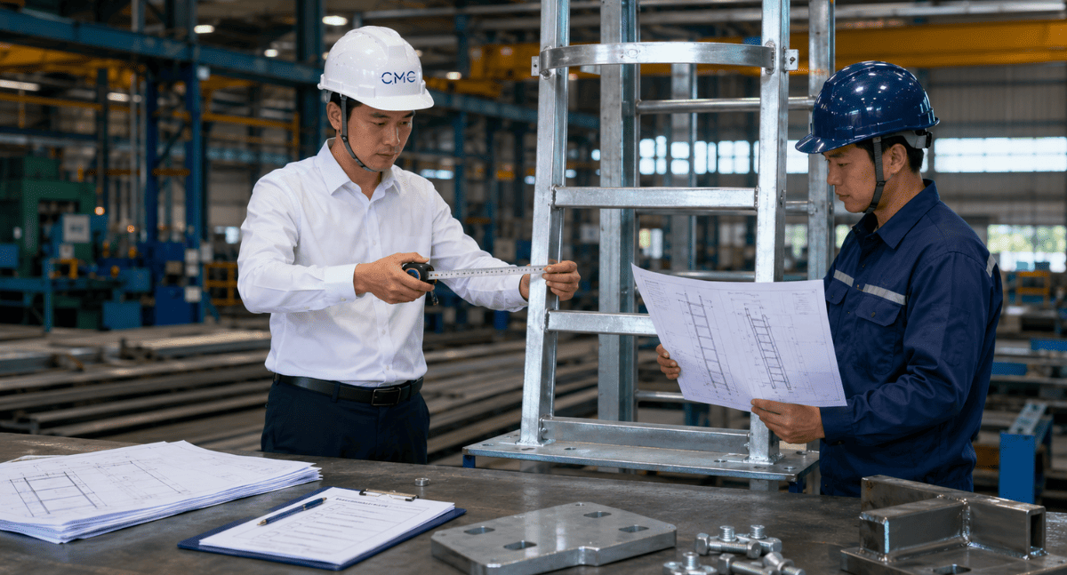
What is a technical ladder

In technical drawings, ladders usually need to be clearly shown:
- Overall height of the ladder.
- Ladder width.
- Distance between steps.
- Dimensions of vertical and horizontal bars.
- Connection points to walls, steel frames, or main structures.
- Details of plates, bolts, and welds.
- Distance of the ladder from the wall or structure behind it.
- Access points at the beginning and end.
- Handrails, handrails, guardrails, or fall protection systems if required by the project.
The clearer the drawing, the smoother the fabrication and installation process of the ladder will be
Why is it necessary to carefully check the dimensions of technical ladder drawings
- The steps are too far apart or uneven.
- The ladder is too narrow, making it difficult to use.
- There is insufficient space between the ladder and the wall for foot placement.
- The bolt or base plate placement is difficult to install.
- The connection details do not match the existing structure.
- The access points are inconvenient or lack handrails.
- The ladder is too high without a safety protection solution shown.
- The dimensions on the drawing do not match the actual site conditions.
Dimensions to check in technical ladder drawings

1. The overall height of the ladder
- At what elevation does the elevator begin?
- Where does the elevator end – on the floor, roof, machine base, or work platform?
- Have the finished elevations been accurately updated?
- Is there a discrepancy between the architectural and structural drawings and the actual site conditions?
- Does the elevator height need to be divided into sections for easier manufacturing, transportation, and installation?
If the overall height is incorrect, the entire step system, the placement of the base plates, and the upper access points may be affected. This is a common error that can occur when the elevator has been fabricated but does not match the actual building specifications.
2. The distance between the steps
When examining drawings, pay attention to the following:
- Distance between the center of each step.
- Uniformity of steps.
- Distance from the floor to the first step.
- Distance from the last step to the top access point.
- Compliance with applicable safety standards for the project.
The manufacturer should not be left to guess the step spacing. This dimension must be clearly indicated on the elevation or detailed specifications of the staircase
3. Ladder width
- The distance between the two vertical bars.
- The clear width for users to climb.
- The width of the ladder rungs.
- The dimensions of the steel bars used for the rungs.
- The compatibility between the ladder width and the actual installation location.
For elevators installed in confined spaces such as technical shafts, elevator wells, behind equipment, or against walls, the width needs to be carefully checked to avoid situations where the drawings are correct but there is insufficient space for installation in reality.
4. Distance from the ladder to the wall or structure behind it
- The distance from the center or edge of the step to the back wall surface.
- Leg space for feet.
- Location of beams, conduits, electrical boxes, equipment, or obstructions behind the stairs.
- Variations in clearance at locations with protruding structures.
For ladders attached to steel frames, panels, concrete walls, or auxiliary structural systems, the details of the support brackets must be clearly shown to ensure stable clearance for use.
5. Dimensions of the vertical and horizontal bars
Vertical and horizontal bars are the two main components that make up a ladder structure. The dimensions of these bars must be appropriate for the ladder height, load capacity, installation conditions, and technical requirements of the project
The drawing should clearly show:
- Steel specifications for the vertical bars.
- Steel specifications for the stair treads.
- Material thickness.
- Type of material used.
- Surface finish options such as painting, galvanizing, or anti-corrosion treatment.
- Technical notes if the ladder is installed outdoors or in a corrosive environment.
Without proper material information, the manufacturer may misinterpret or use inappropriate specifications. This directly affects the durability and lifespan of the elevator.
6. Location of base plates, bolts, and connecting details
Technical ladders are typically attached to walls, steel frames, columns, beams, or work platforms using plates, bolts, welding, or anchoring devices. This is a section that requires very careful inspection in the shop drawing.
A good drawing should clearly show:
- Position of each base plate.
- Base plate dimensions.
- Base plate thickness.
- Number and diameter of bolts.
- Bolt hole spacing.
- Welding location or weld length.
- Distance from base plate to structural edge.
- Type of connection to the main structure.
If the base plate is not positioned correctly, the construction team may encounter difficulties when drilling, tightening bolts, or welding on-site. If the base plate overlaps with reinforcing steel, technical pipes, or if there is insufficient working space, installation will become problematic.
Therefore, the details of the connection should not be shown superficially. Cross-sections, magnified details, and clear annotations are necessary.
7. The locations of the elevator's ascent and descent points
A safe climbing ladder depends not only on the ladder itself, but also on the access points. Users need convenient space to begin and end the climb
The following information needs to be checked in the drawing:
- Clearance at the base of the ladder.
- Floor elevation at the starting point.
- Position of the first step relative to the floor.
- Working space at the point of access to the roof or work platform.
- Handrail or extension of the ladder at the upper access point.
- Connection between the ladder and the work platform.
If the top access point is too narrow or lacks a suitable handrail, users may have difficulty transitioning from the ladder to the platform. This detail should be considered during the design phase and not delayed until construction begins
8. Dimensions of the protective frame or fall protection system, if any

- Diameter or dimensions of the frame.
- Distance from the ladder to the guardrail.
-Start and end positions of the frame.
- Distance between frame loops.
- Vertical connecting bars.
- Details of the connection between the guardrail and the ladder.
- Exit space at the top access point.
If a fall protection system is used, the drawings must incorporate equipment information, anchoring locations, guide rails, or other relevant technical requirements. This section requires careful verification between the design, safety, and equipment supplier, if applicable
9. Gaps around the ladder
Technical ladders are often installed in areas with numerous other systems such as air ducts, water pipes, electrical cables, steel beams, panels, louvers, machinery, or industrial pipelines. Therefore, the clearance around the ladder is very important
The drawing needs checking:
- Gaps on either side of the ladder.
- Gap in front of the ladder.
- Obstacles behind the ladder.
- Space for climbers to turn or step out.
- Space for routine maintenance and inspection.
- Conflicts with other engineering systems.
If the project uses a BIM model, it's advisable to check the elevator in 3D space to detect conflicts early. This helps prevent situations where elevator obstructions from equipment, beams, pipes, or other structures are only discovered on-site.
10. Manufacturing and installation tolerances
- Overall height tolerance.
- Base plate position tolerance.
- Bolt hole tolerance.
- Step spacing tolerance.
- Adjustability during installation.
- Conditions for minor discrepancies in site conditions.
The drawings should clearly show the locations that need to be inspected before mass production or installation.
The role of AutoCAD 2D in engineering ladder drawings.
- The manufacturing workshop understands the correct elevator structure.
- The construction team knows the installation location.
- Engineers can check important dimensions.
- The investor can easily visualize the project.
- Minimizes discrepancies in manufacturing and installation.
However, 2D AutoCAD drawings need to be standardized in terms of layers, lines, symbols, notes, and versions. If the drawing is unclear or inconsistent, the ladder may still malfunction even if it has been represented in a technical drawing.
The role of BIM in engineering ladder inspection
- Conflicts between the ladder and the steel structure.
- Conflicts between the ladder and the MEP system.
- Access clearances around the ladder.
- Location of access to the roof, work platform, or equipment.
- Coordination between the ladder, handrail, work platform, louver, panel, and steel frame.
When AutoCAD 2D and BIM are combined effectively, stairwell drawings are not only more detailed but also more accurate in terms of the overall spatial layout of the building
CMC Architects Vietnam provides support in the implementation of professional technical staircase drawings
- Technical ladders.
- Steel railings.
- Handrails.
- Steel staircases.
- Louvers.
- Panels.
- Steel frames.
- Base plates.
- Connecting bolts.
- Other architectural metal details.
We prioritize checking the dimensions, connection details, construction conditions, manufacturing feasibility, and consistency of the drawings before handover. The goal is to ensure the drawings are easy to read, easy to manufacture, easy to install, and support safer project operation
Conclude
- 📞 Hotline: 0936361299
- 📧 Email: cmc.vn1013@gmail.com
- 🌐 Website: https://cmcarchitects.com/
- 📍 Address: 79A Xuan La, Tay Ho, Hanoi


