In every construction project, floors and railings are not only functional elements but also play a crucial role in ensuring safety, aesthetics, and long-term durability. Especially for projects involving steel, architectural metals, or auxiliary structures, a clear and accurate set of drawings will facilitate a smoother construction process, minimize errors, and reduce unforeseen costs.
At CMC Architects Vietnam, we understand that drawings are not just technical documents, but also a "common language" connecting the investor, design firm, contractor, manufacturer, and construction team on site.
A professional set of floor and railing drawings should include complete information such as: overall floor plan, elevations, sections, connection details, dimensions, heights, materials, installation locations, and the actual construction plan. When this information is presented clearly, the construction team can easily understand it, manufacture the products to the correct dimensions, and install them accurately on site.
Why Do Floor and Railing Designs Need to Be Detailed?
Floors and railings are items frequently and directly involved in human use. Even a small deviation in size, height, connection position, or component spacing can affect safety, aesthetics, and construction progress.
An unclear drawing can cause the construction team to spend extra time rechecking, requesting clarification, or even re-fabricating details. This not only slows down progress but also increases project costs beyond expectations.
Conversely, when the drawing is complete, from floor plan to detail, clearly showing the position of each railing, support, base plate, bolt, weld, and connection detail, the manufacturing workshop can fabricate accurately, the construction team can easily install, and the investor can be more confident in the quality of the finished product.
Floor Plan: The Foundation for Determining Overall Location and Dimensions
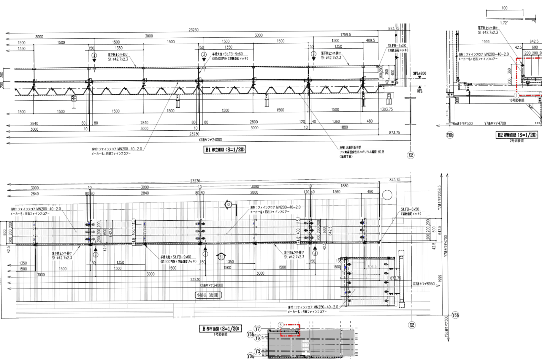
In floor and railing drawings, the floor plan helps viewers visualize the overall installation location of the entire project. Information such as railing length, distance between connection points, floor layout orientation, elevation, and positioning axes must be clearly shown.
At CMC Architects Vietnam, floor plans are always designed to be easy to read, with clear dimensions and consistent with other projections. This allows project participants to quickly check information and compare the drawings with the construction site.
Elevation View: Shows the Shape, Height, and Proportions of the Balustrade
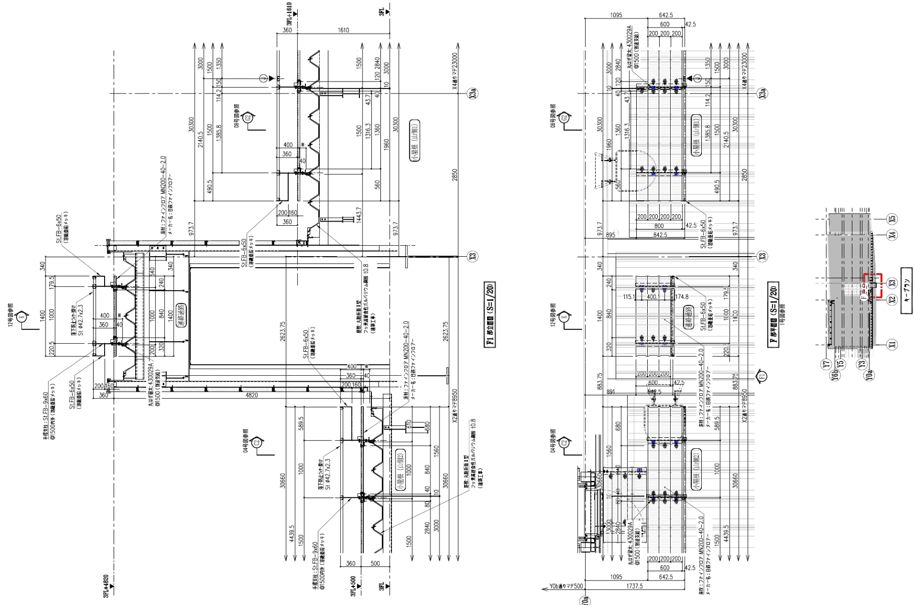
While floor plans define the overall layout, elevations clearly show the external shape, height, and proportions of the railing system. This is a crucial part of the drawing for checking railing height, spacing of vertical bars and handrails, connection points, and aesthetic consistency.
A good elevation drawing should help viewers understand the complete picture of the finished project. For steel or metal railings, elevations also help control alignment, even spacing, and accuracy between installation sections.
When elevations are clearly shown, the production team can fabricate to scale, and the construction team can quickly check the installation location on site. This is a key factor in creating a clean, sturdy, and professional-looking finished project.
Cross-Section: Clarifying Structure and Technical Connections
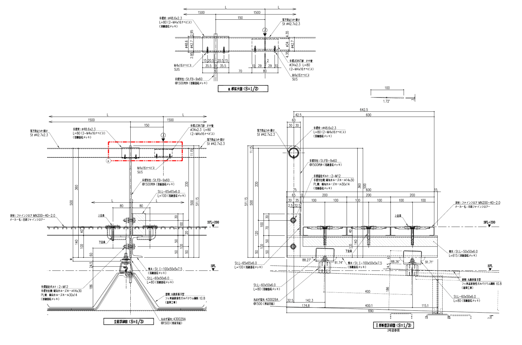
In engineering drawings, cross-sections clarify information that floor plans or elevations cannot fully show. For floor and railing elements, cross-sections typically show the floor structure, the connection points between the railing and the floor, details of bolts, base plates, support beams, or auxiliary steel components.
This is particularly important for the manufacturing workshop and construction team. Without clear cross-sections, determining height, spacing, drilling locations, or fixing methods can be very difficult.
A detailed cross-section will help answer important questions such as:
Where are the railings connected?
What are the dimensions and positions of the base plates?
How are bolts, screws, or welds arranged?
Are the floor and handrail elevations correct?
Are the spacing between components appropriate for actual construction?
This information makes the drawings more valuable during the construction process.
Technical Details: Factors Determining Machining and Installation Accuracy
In a professional set of drawings, the technical details section always plays a crucial role. This is where small details that significantly impact construction quality are shown, such as base plate dimensions, drilling locations, material type, bolt sizes, connection spacing, installation direction, and technical notes.
For flooring and railing projects, technical details minimize misunderstandings. When details are clearly presented, the production team can accurately fabricate from the start, avoiding rework in the workshop or multiple adjustments on site.
This also demonstrates the professionalism of the drawing implementation unit. A well-designed drawing is not only about a neat layout but also about its ability to accurately convey technical information to the user.
The Benefits of Clear Floor and Railing Drawings
A well-executed set of drawings offers numerous practical benefits for the entire project.
First, clear drawings help reduce errors during production and construction. When dimensions, materials, and installation locations are fully shown, all parties involved can work together more effectively.
Next, detailed drawings save time on communication and inspection. The construction team doesn't need to spend excessive time asking for clarification or resolving unclear points on site.
Furthermore, professional drawings help control the quality of the finished product. The consistent implementation of details for railings, floors, handrails, supports, and connections ensures higher accuracy and aesthetics in the final construction.
Most importantly, clear drawings build trust among all parties involved in the project. When the investor, contractor, and construction team work together on a unified set of technical documents, the implementation process becomes more transparent, efficient, and professional.
CMC Architects Vietnam – Partnering in Steel Structure Design
CMC Architects Vietnam specializes in developing technical drawings for steel and metal architectural structures such as railings, handrails, steel staircases, steel floors, ladders, panels, louvers, door frames, and other auxiliary details.
With experience in using AutoCAD 2D, combined with a strong technical control mindset and the ability to understand real-world construction requirements, we always aim to create clear, accurate, and user-friendly drawings.
Each drawing at CMC Architects Vietnam is developed with meticulous care: from layout and presentation, dimensioning, material notes, connection details, to the consistency between floor plans, elevations, sections, and details.
We believe that a good drawing not only ensures the correct execution of the construction but also contributes to the professionalism of the entire construction process
Conclude
Floor and railing drawings are a crucial part of a construction project's technical documentation. When fully and accurately prepared, these drawings facilitate the manufacturing, fabrication, and installation process, minimizing errors, saving time, and improving the overall quality of the finished product.
If you need assistance in developing technical drawings for your floor, railing, handrail, steel staircase, or other architectural metal structures, CMC Architects Vietnam is ready to partner with you on every detail of the drawings.
What do you consider most important in a set of technical drawings: clear dimensions, detailed connection information, or feasibility of construction? Share your perspective to discuss how to create a more professional set of drawings.
- 📞 Hotline: 0936361299
- 📧 Email: cmc.vn1013@gmail.com
- 🌐 Website: https://cmcarchitects.com/
- 📍 Address: 79A Xuan La, Tay Ho, Hanoi


