In modern construction projects, stair railings are not only safety elements that support daily movement, but also an important part of the overall architectural quality. Especially on the second floor, where railings are often connected directly to the floor slab, corridor, staircase, bridge area, or supporting steel components, fabrication and construction drawings must be developed clearly, accurately, and in a way that is easy to review.
At CMC Architects Vietnam, we understand that a good drawing set is not only about showing the correct shape of a component. More importantly, the drawings must help the fabrication workshop produce components with the correct dimensions, support the construction team in installing them in the right position, and allow all related parties to control quality before actual installation on site.
For the scope of fabrication and construction drawings for second-floor stair railings in Areas A & B, key information such as the overall plan, area plans, elevations, sections, post details, base plates, bolts, module spacing, and connection positions must be presented consistently. This is an important foundation that helps production, fabrication, and installation proceed more smoothly while reducing errors and improving the quality of the finished work.
Why Second-Floor Stair Railing Drawings for Areas A & B Need to Be Detailed
Stair railings are directly related to user safety. Even a small error in height, post spacing, base plate position, floor level, or connection method can affect stability, appearance, and construction progress.
For second-floor areas, the railing system often includes long railing runs, repeated modules, transition points, and multiple connections with surrounding structures. If the drawings are not clear enough, the installation team may have difficulty identifying exact installation positions, while the fabrication workshop may produce components with incorrect dimensions or require multiple adjustments when the components are delivered to the site.
On the other hand, when the drawings are developed completely from plans to technical details, every important piece of technical information can be controlled in advance. This helps all parties work with the same understanding, reduces coordination time, minimizes unexpected issues, and creates a more professional construction process.
Overall Plan Drawing: Defining the Second-Floor Railing Scope
The overall plan drawing helps viewers understand the full scope of the second-floor stair railing system in Areas A & B. This drawing is important for identifying the railing route, bridge area, starting and ending points of each railing section, and the relationship between the railing system and the surrounding space.
For railing systems with long spans and repeated sections, the overall plan helps the construction team quickly check the installation scope. At the same time, the fabrication workshop can use this drawing to divide railing sections, assign component codes, and prepare a suitable fabrication plan.
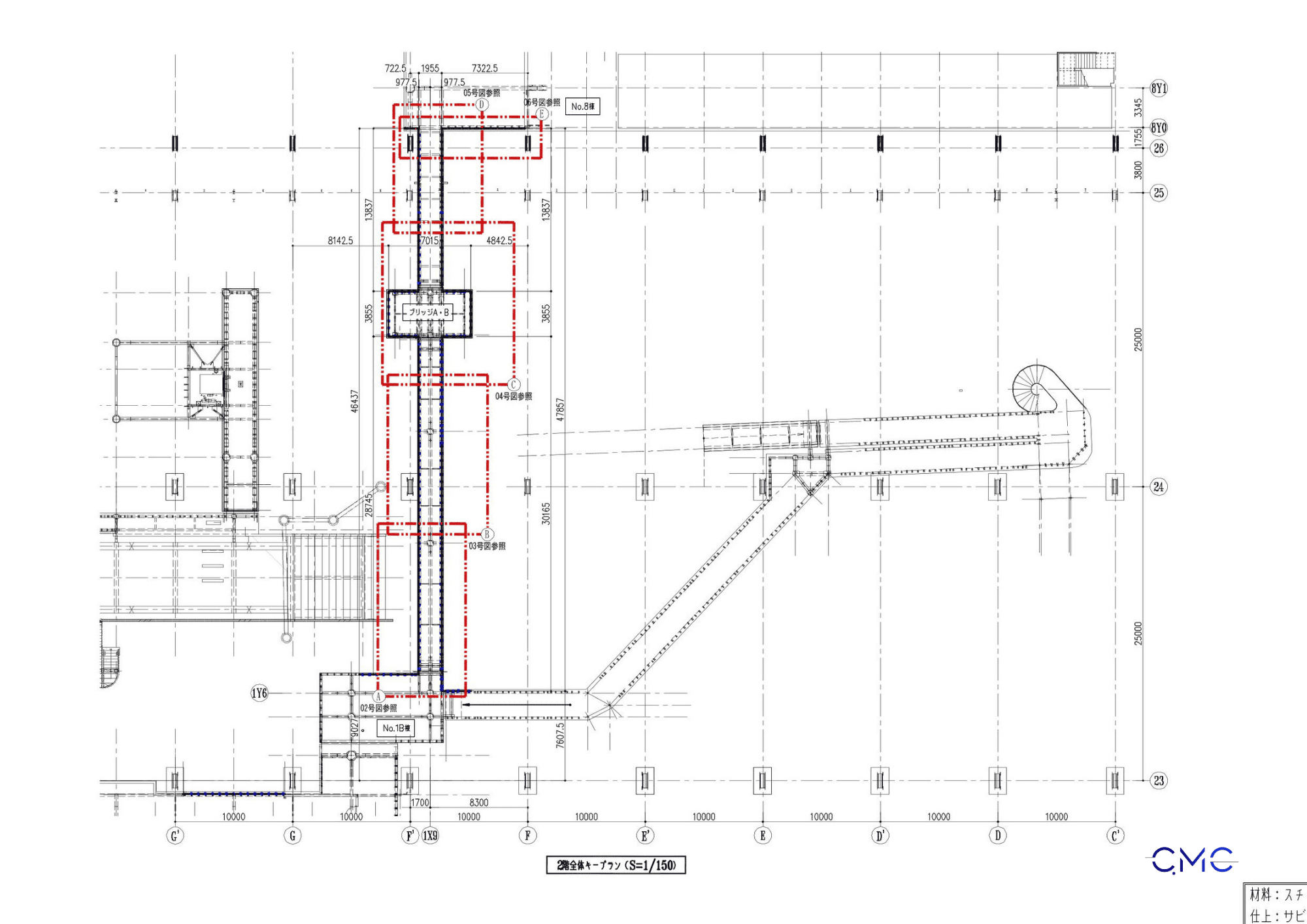
The overall second-floor plan shows the construction scope of the stair railings in Areas A & B, helping control installation positions and areas requiring detailed development.
Area A Plan Drawing: Controlling Installation Positions and Module Spacing
After the overall plan, the Area A plan drawing clarifies each railing section within a specific area. The drawing shows post positions, module spacing, connection points, overall dimensions, and installation scope in a clear and organized way.
This part is especially important for the construction team because it helps determine drilling positions, base plate locations, and spacing between components. When the Area A plan is clearly presented, comparing the drawing with actual site conditions becomes faster, more accurate, and less risky.
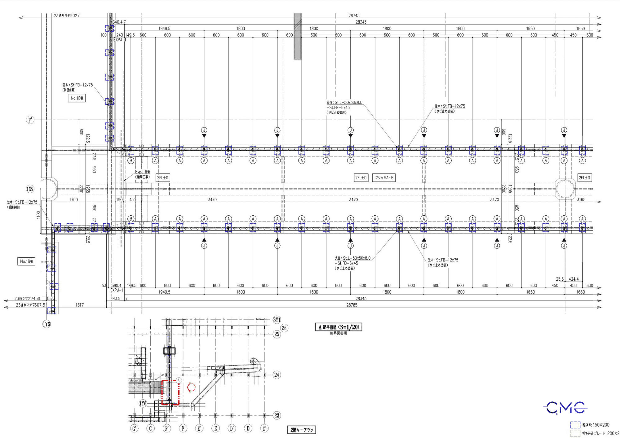
The Area A plan drawing shows railing installation positions, module spacing, and key connection points for construction.
Area B Plan Drawing: Ensuring Consistency Between Railing Sections
In addition to Area A, the Area B plan drawing should also be shown separately to fully control the construction scope. Area B usually includes continuous railing sections, repeated post positions, and connection areas that need careful checking.
Separating Area B in the drawing set makes the information easier to follow and helps avoid confusion between railing sections that may have similar configurations but different installation locations. This is an important factor in the production of steel components, especially when there are many repeated parts and high accuracy is required.
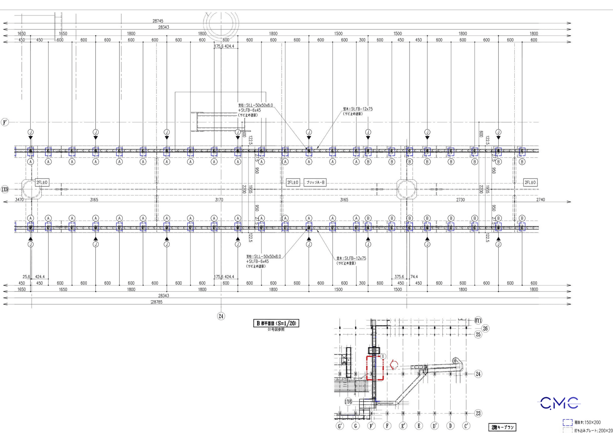
The Area B plan drawing helps control construction scope, railing post positions, and consistency between installation sections on the second floor.
Central and Transition Area Plans: Controlling Important Technical Intersections
In the second-floor railing system, central areas, transition zones, and bridge connection areas often include many technical intersections. These are locations where errors can easily occur if dimensions, levels, and connection details are not clearly shown.
The plan drawings of these areas help clarify how different railing sections meet, how posts are arranged, and how the railing system connects with surrounding structures. This allows the site team to review critical locations before installation and gives the fabrication workshop a clear basis for preparing each component correctly.

The transition area plan clarifies technical intersections, connection positions, and railing installation scope on the second floor.
Elevations and Sections: Clarifying Height, Structure, and Fixing Method
If plan drawings define the position, elevations and sections help control the shape, height, and actual structure of the railing system. This part is important for identifying railing height, post dimensions, horizontal members, handrails, base conditions, and fixing methods to the second-floor slab.
For the second-floor stair railings in Areas A & B, elevations and sections also show how the railing posts are fixed to the floor, how base plates are arranged, and how steel components are connected together. These details help reduce errors during fabrication and support the installation team in following the correct construction method.

Elevation and section drawings show railing height, post structure, base conditions, and the connection method to the second-floor slab.
Post and Base Plate Details: Key Factors for Accurate Installation
In fabrication and construction drawings for railings, post and base plate details are essential. These details show important information such as base plate dimensions, bolt positions, hole spacing, anchor depth, materials, and fixing methods to the structure.
A small error in the post or base plate detail can cause the railing to misalign during installation, forcing the construction team to drill again or adjust components on site. This not only takes additional time but can also affect the quality of the finished work.
Therefore, CMC Architects Vietnam pays close attention to presenting connection details clearly, readably, and practically. Every dimension, symbol, and technical note is arranged to support fabrication and real on-site installation as effectively as possible.
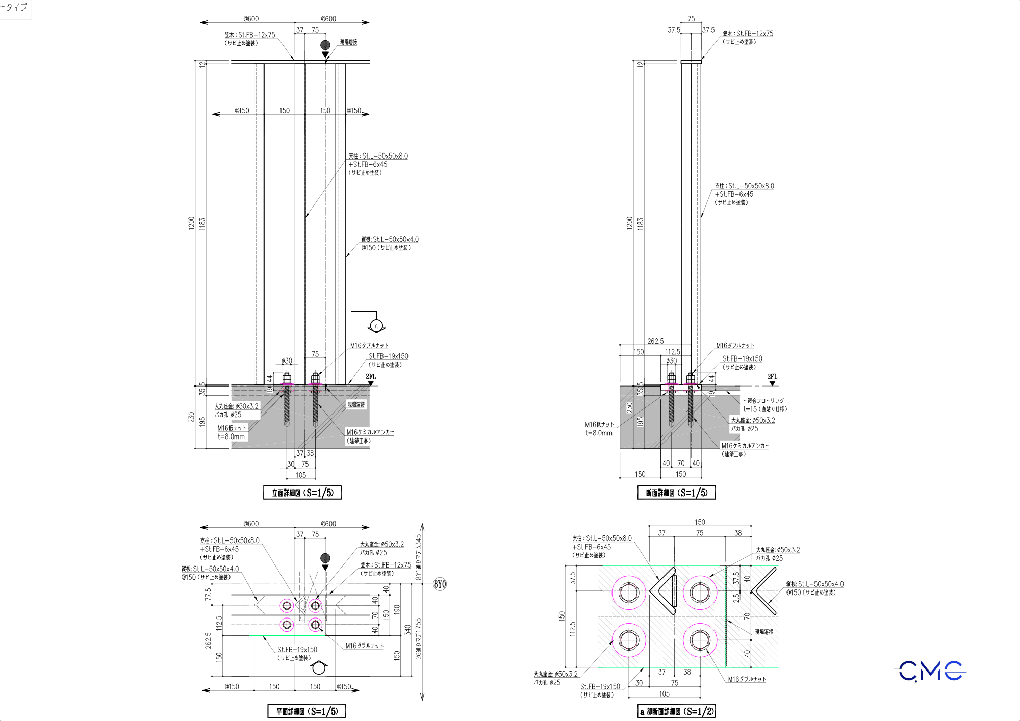
Post and base plate details show bolt positions, connection dimensions, and fixing methods for securing the railing to the floor structure.
Enlarged Details: Supporting Accurate Fabrication of Each Component
For architectural metal works, enlarged details play a very important role in the production process. Information such as steel dimensions, welding positions, screw positions, edge distances, connection configuration, and installation direction must be clearly shown to prevent misinterpretation.
For the second-floor stair railings in Areas A & B, enlarged details help the fabrication workshop understand each component before production. At the same time, the construction team can use these details to check complex connection points before installation on site.
This is one of the elements that reflects the professionalism of a drawing set. A good drawing set should not only provide a clear overall plan, but also explain every important technical detail required for accurate fabrication and installation.
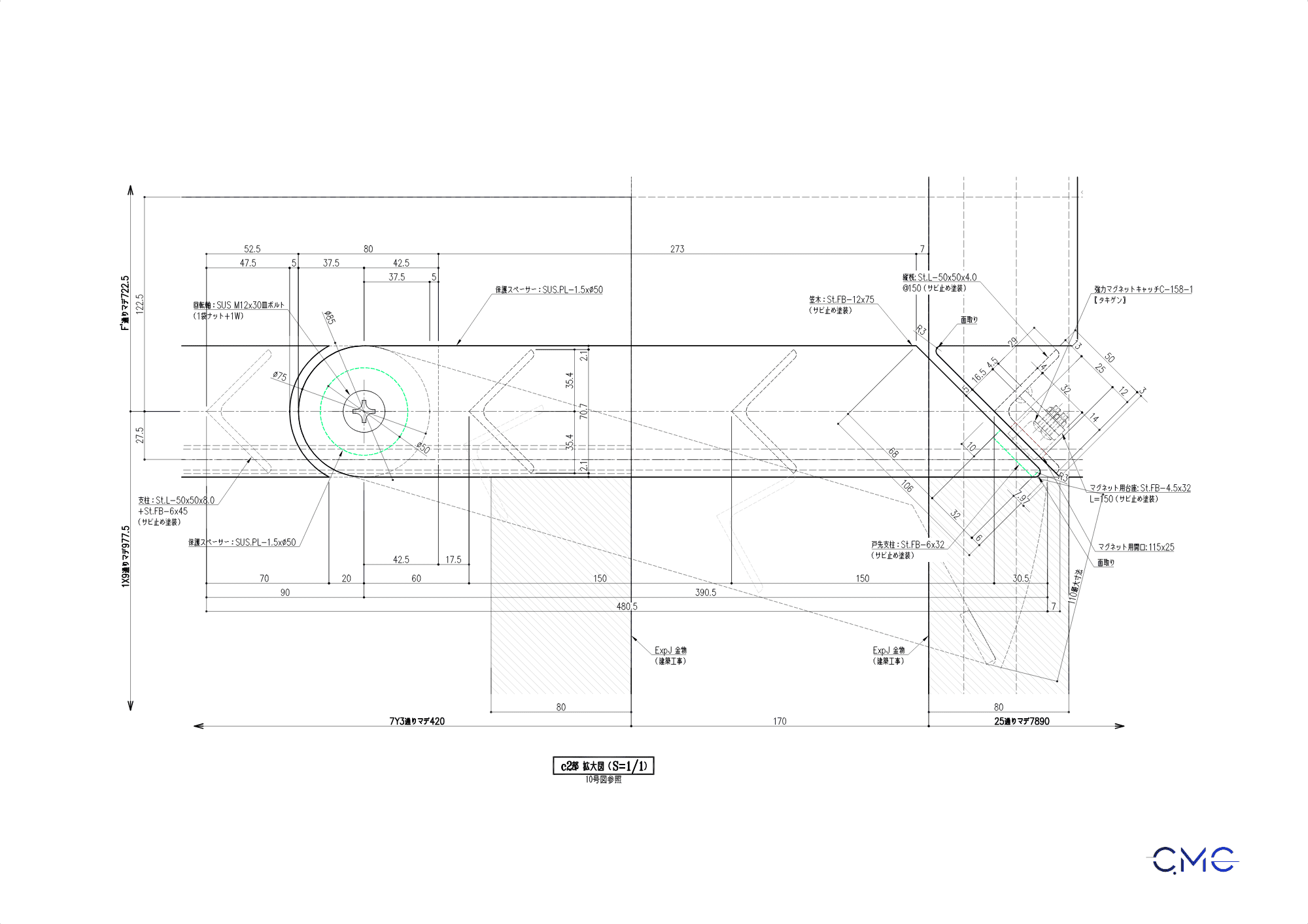
Enlarged connection details help control component dimensions, connection positions, and fabrication methods for the second-floor railing system.
Benefits of a Professional Stair Railing Drawing Set
A professionally developed fabrication and construction drawing set for second-floor stair railings brings many practical benefits to a project.
First, clear drawings help reduce errors during fabrication and installation. When dimensions, materials, levels, and connection positions are fully shown, all related parties can work from the same technical information.
Second, detailed drawings help save time in checking and coordination. The construction team does not need to spend too much time asking for clarification or resolving unclear issues on site.
In addition, accurate drawings help control the quality of the finished work. Each railing post, handrail, horizontal member, base plate, and connection point is coordinated consistently, helping the completed railing system achieve better stability, neatness, and visual quality.
Most importantly, a professional drawing set helps build trust between the client, design team, fabrication workshop, and construction team. When all technical information is presented transparently, the project process becomes more efficient, less risky, and more professional.
CMC Architects Vietnam – Your Partner in Fabrication and Construction Drawing Design
CMC Architects Vietnam specializes in developing technical drawings for steel works and architectural metal components, including railings, handrails, steel stairs, technical ladders, steel floors, panels, louvers, frames, and supporting connection details.
With experience in AutoCAD 2D, technical coordination, and practical construction understanding, we aim to create drawing sets that are clear, accurate, and easy to use in real construction conditions.
In every drawing set, CMC Architects Vietnam focuses on consistency between plans, elevations, sections, and technical details. This helps reduce errors, support efficient production, and improve construction quality on site.
We believe that a good drawing not only helps a project be built correctly, but also contributes to a more professional workflow, saves time, and increases the overall value of the project.
Conclusion
Fabrication and construction drawings for second-floor stair railings in Areas A & B are an important part of the project’s technical documentation. When developed completely, clearly, and accurately, they help production, fabrication, and installation proceed more smoothly while reducing errors, saving time, and improving the quality of the finished work.
For CMC Architects Vietnam, every drawing is not just a technical document. It is also a commitment to accuracy, professionalism, and responsibility in every detail.
Which factor do you think is the most important in a professional stair railing drawing set: clear plans, accurate elevations, complete sections, or buildable connection details? Share your thoughts with CMC Architects Vietnam and let’s discuss how to create more effective and professional technical drawings for construction projects.
Contact Information
CMC Architects Vietnam
Website: https://www.cmcarchitects.com/
Hotline: 0936361299


