In every construction project, stair railings are not only a safety feature but also contribute to the overall perfection, neatness, and professionalism of the architectural space. Especially in projects using steel structures or metal components, the construction and fabrication drawings for stair railings play a crucial role in controlling dimensions, materials, connection methods, and the quality of actual installation.
At CMC Architects Vietnam, we understand that a good set of drawings needs to be not only technically correct but also easy to read, easy to check, and effectively applicable during production, fabrication, and construction on site.
For stair railing construction and fabrication drawings, information such as floor plans, elevations, sections, handrail details, railing posts, base plates, bolts, anchor points, elevations, and component spacing must be clearly shown. When this information is tightly controlled, the production team can manufacture precisely, the construction team can install smoothly, and the investor can have greater peace of mind regarding the quality of the finished product.
Why are construction and fabrication drawings for stair railings important
Stair railings are a crucial element directly related to safety. Even a small deviation in handrail height, vertical spacing, post position, or connection details can affect structural integrity, aesthetics, and construction progress.
In practice, unclear drawings can lead to incorrect dimensions from the manufacturer, misplaced installation by the construction team, or multiple on-site adjustments. This not only increases costs but also impacts project completion timelines.
Conversely, a complete set of construction and fabrication drawings facilitates better collaboration among all parties involved. From floor plans, elevations, and cross-sections to connection details, all information is clearly presented to directly support the fabrication and installation process.
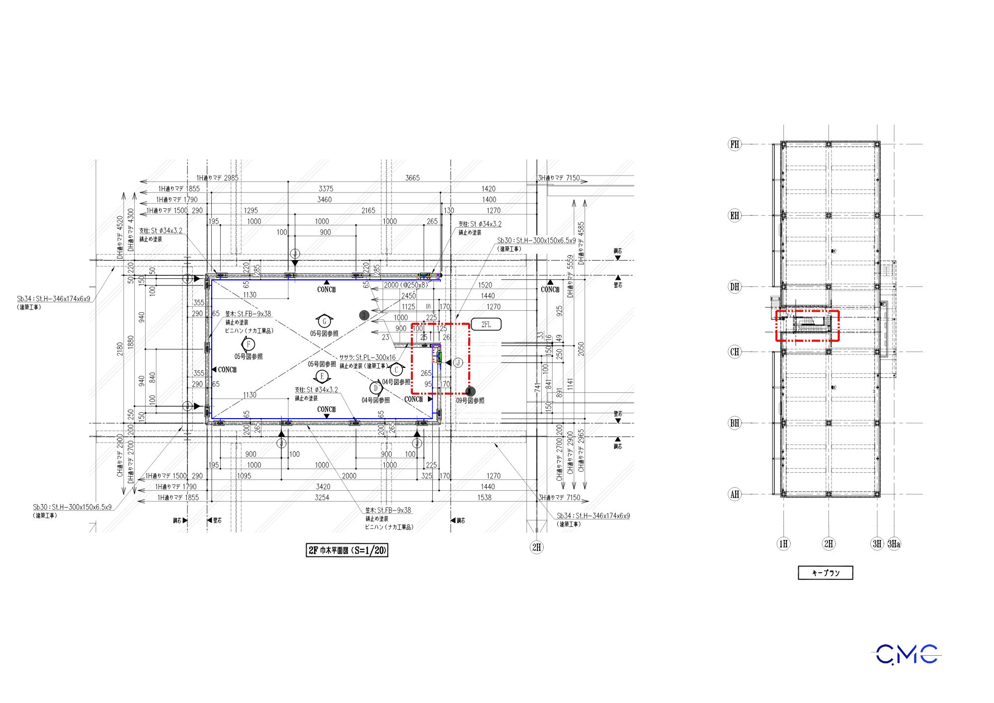
Floor Plan: Determining the Location and Scope of Railing Installation
The floor plan helps viewers visualize the overall installation location of the stair railing in the building. Information such as the staircase orientation, handrail location, start and end points of the railing, alignment axes, overall dimensions, and connection points should be clearly shown.
This is a crucial basis for the construction team to compare the drawing with the site. When the floor plan is fully presented, determining the installation location becomes faster and more accurate, minimizing discrepancies between the drawing and the actual construction.
For stair railing projects with multiple floors or multiple turns, the floor plan needs even more careful control. Dividing the plan into sections, marking connection points, and clearly showing the construction scope helps to ensure a more synchronized fabrication and installation process.
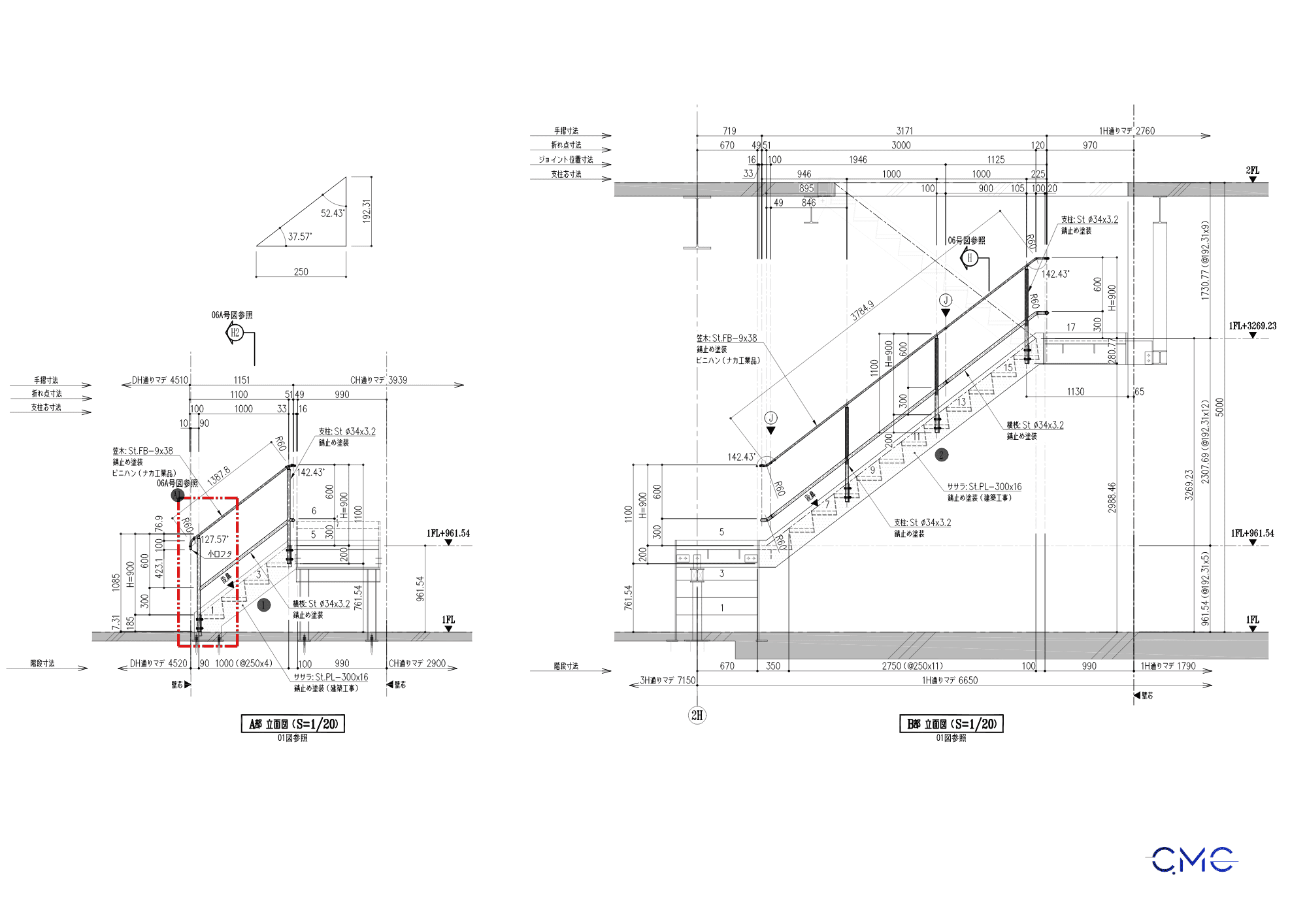
Elevation View: Controlling the Shape, Height, and Slope of the Balustrade
While the floor plan helps determine the overall layout, the elevation view controls the final shape of the railing system. This is crucial for checking handrail height, stair slope, post spacing, crossbar placement, and the continuity of the entire railing system.
For stair railings, the elevation view should clearly show the relationship between the handrail, stair treads, floor level, and surrounding structures. This allows the construction team to easily visualize the finished railing shape and check important elevations before installation.
A clear elevation drawing also helps the fabrication workshop ensure the correct proportions, lengths, and bending or joining positions of each component. This is essential for the railing to be properly aligned, sturdy, and aesthetically pleasing after installation.
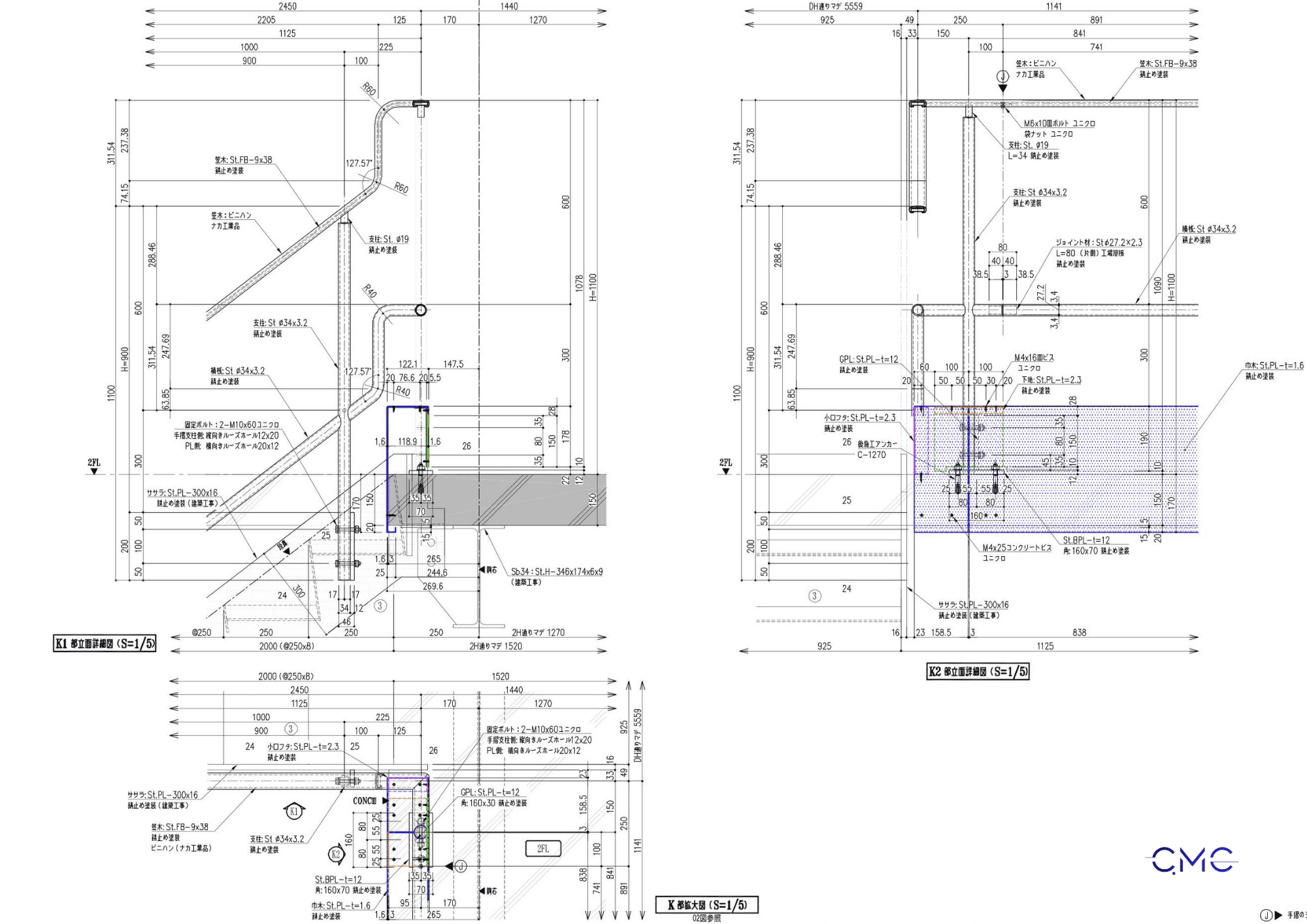
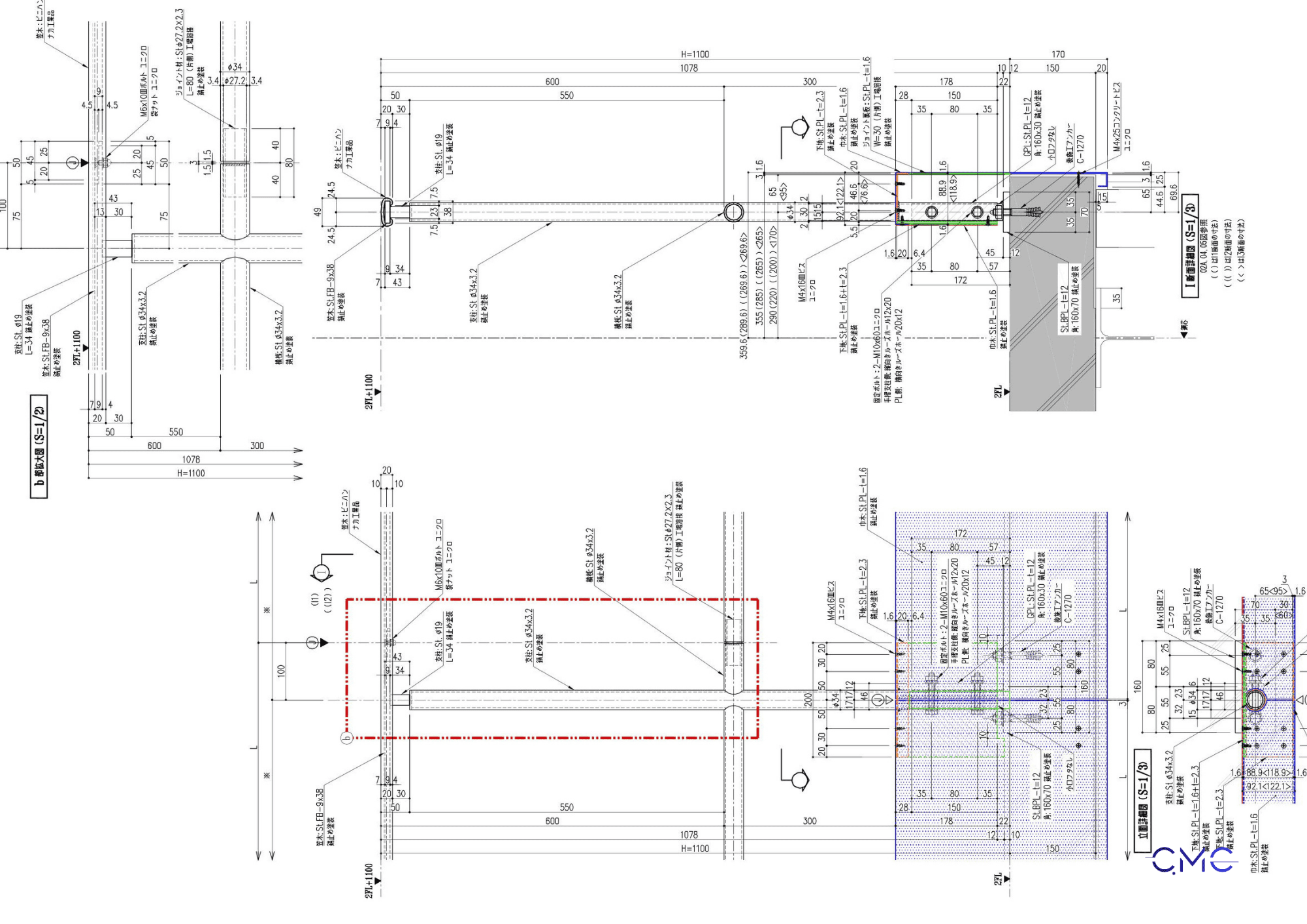
Cross-Section: Clarifying the Structure and Connection Scheme
Cross-sections clarify information that floor plans and elevations may not fully show. For stair railing drawings, cross-sections typically show how the railing is connected to the floor, walls, steps, or surrounding steel structure.
This is particularly important during construction, as it helps determine the precise anchor locations, distances from the floor edge to the connection points, installation height, base plate construction, bolt type, and fixing method.
If the cross-sections are unclear, the construction team may have difficulty identifying drilling locations, bolt placement, or handling intersections. Therefore, showing complete cross-sections helps minimize errors and reduce the risk of on-site adjustments.

Technical Details: The Foundation for Precision Machining
Manufacturing Drawings: The Bridge Between Design and Production
Benefits of a Professional Set of Staircase Railing Drawings
CMC Architects Vietnam – Partnering in Construction Drawing Design and Fabrication
Conclude
Contact Information
CMC Architects Vietnam
Website: https://www.cmcarchitects.com/
Hotline: 09.3636.1299


