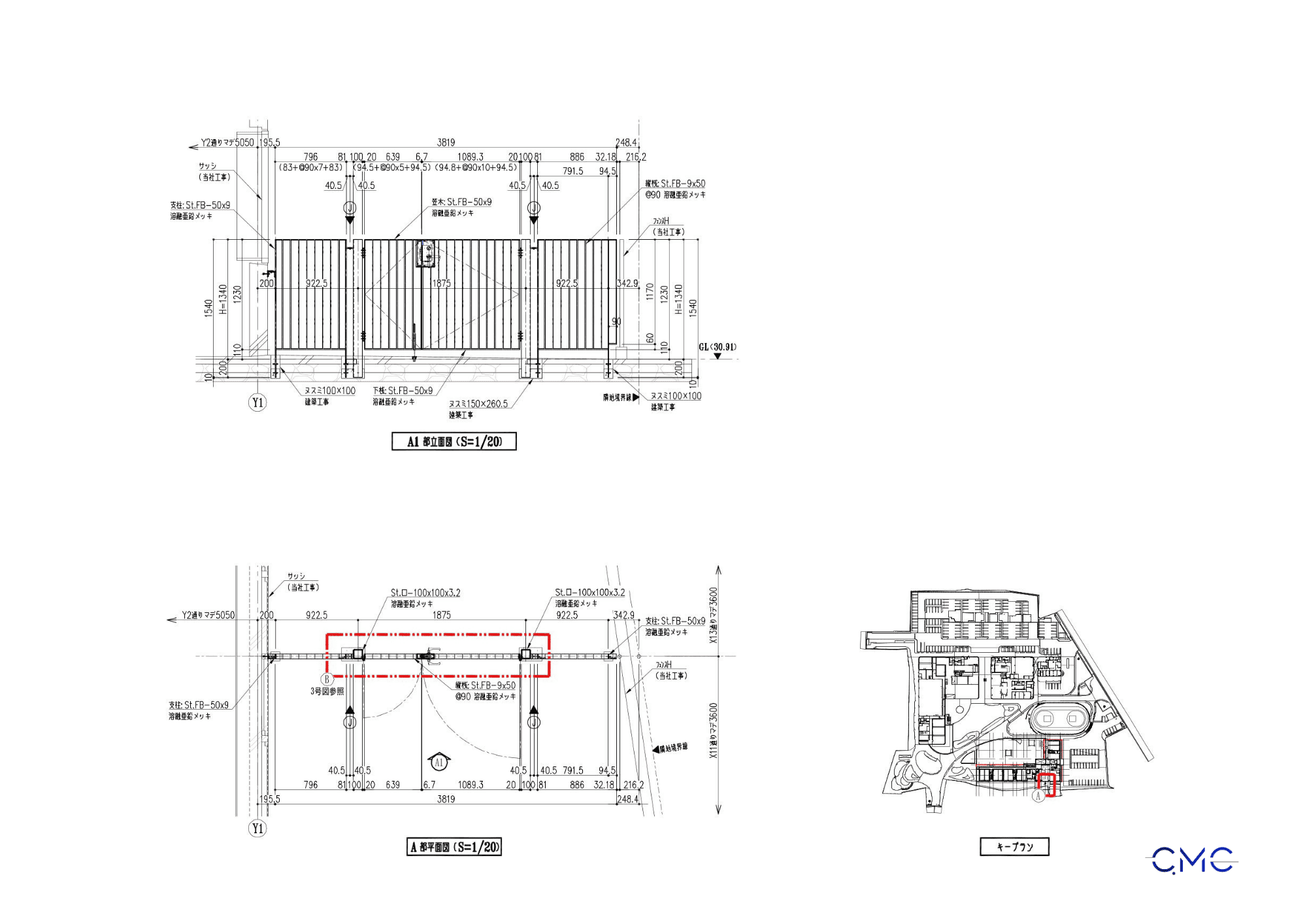
In industrial buildings, technical areas, factories, equipment rooms, rooftop access zones, and maintenance spaces, a steel ladder may look like a small structural element, but it plays an important role in daily operation, inspection, and maintenance. To ensure safe installation, accurate fabrication, and long-term usability, every steel ladder should begin with a clear, detailed, and well-coordinated technical drawing set.
At CMC Architects Vietnam, we understand that a good drawing is more than a visual document. It is a technical foundation that connects design intent, fabrication requirements, and on-site installation. From plan views and elevations to sections and connection details, every drawing must help fabricators, installers, and project teams understand exactly what needs to be produced and installed.
1. What Is a Steel Ladder and Why Does It Need Detailed Fabrication Drawings?
A steel ladder is commonly used in technical spaces such as machine rooms, rooftop areas, maintenance zones, service shafts, factory areas, electrical rooms, and access points that require regular inspection or equipment operation. Unlike a conventional staircase, a steel ladder is usually compact, functional, and highly dependent on accurate dimensions, connection points, and installation conditions.
A proper steel ladder drawing set should not only show the overall shape. It must clearly define the ladder position, total height, rung spacing, side members, steps, steel plates, bolts, anchors, removable handholds if required, and connection details to surrounding structures such as concrete walls, floors, beams, or steel frames.
Without sufficient drawing information, fabrication and installation can easily face problems. For example, anchor positions may be incorrect, rung spacing may not match the design, installation levels may conflict with finished floor levels, or fabricated steel components may not fit properly on site. That is why a detailed drawing set is essential for controlling quality, reducing mistakes, and improving construction efficiency.
2. Overview of the Steel Ladder Drawing Set
The general drawing sheets help project teams understand the project scope, drawing type, material specifications, surface finish, and key fabrication requirements. This information is important before reviewing each technical detail.
For a steel ladder package, specifications such as steel profiles, steel plates, ladder rungs, mounting plates, bolts, anchors, handrails, and protective elements should be clearly noted. A material schedule or specification table helps the fabrication team confirm the correct material before production.
In this drawing set, the steel components are presented with a strong focus on real fabrication and installation conditions. Material, dimension, and finishing information are arranged to support accurate manufacturing and quality checking.
3. Plan and Elevation Drawings – Defining Position, Level, and Ladder Layout
For steel ladders, plan and elevation drawings are essential for identifying the exact installation location within the building. The plan view shows where the ladder is located in relation to grids, walls, floors, structural elements, or technical areas. The elevation view shows the ladder height, rung layout, connection points, and relationship with floor levels.
A clear elevation drawing helps the construction team understand the overall height of the ladder, start point, end point, rung spacing, and fixing locations. This is especially important for avoiding incorrect installation levels or inconsistent ladder spacing during construction.
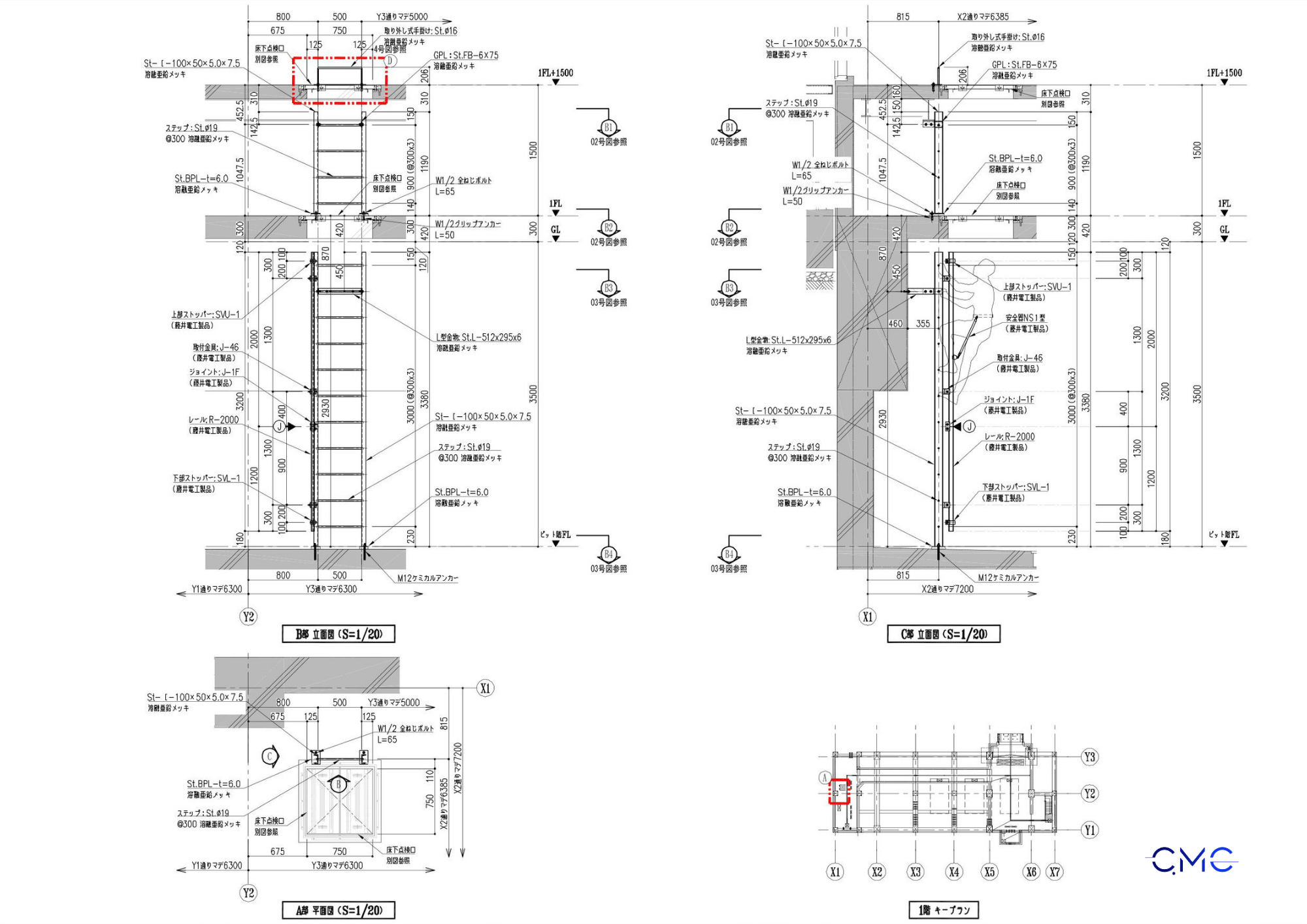
The drawings depict the ladder from multiple perspectives. The elevation view shows the ladder's structure vertically, while the smaller plan view below helps determine its installation position within the overall structure. This presentation is essential so that the construction team can not only see the details but also understand their position in the real-world space.
4. Section Drawings – Clarifying Connection and Installation Conditions
If plan and elevation drawings show the position and form, section drawings explain the technical structure behind the installation. For a steel ladder, section drawings usually clarify how steel members connect to mounting plates, bolts, anchors, concrete walls, floor slabs, or nearby steel structures.
The clearer the section drawings are, the easier it becomes for the fabrication and installation teams to understand assembly sequence, plate thickness, clearance, welding positions, hole locations, and fixing methods. These drawings also help reduce unnecessary discussions on site because the connection details have already been clearly defined.
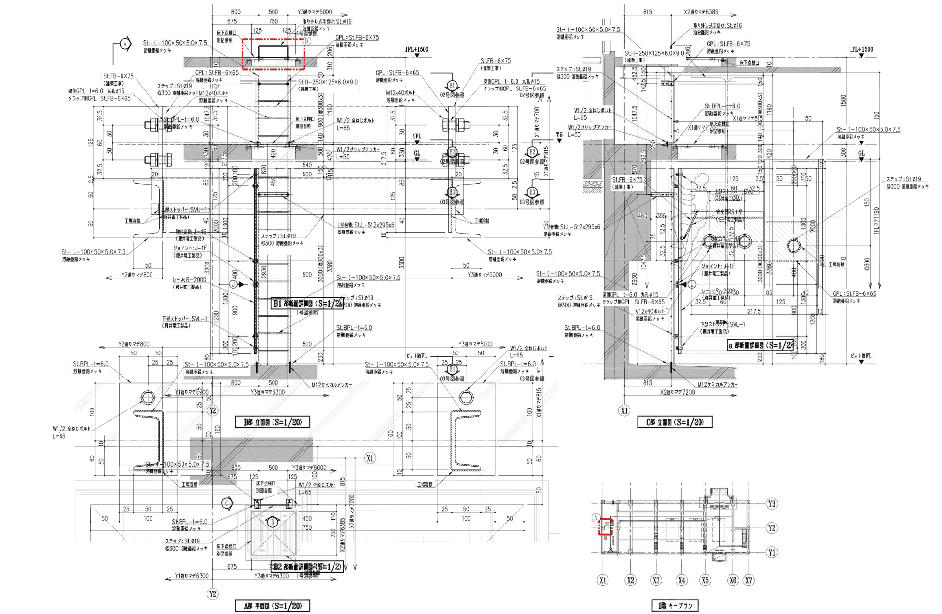
Connection points are shown with various specifications such as base plates, bolts, steel plates, steel profiles, and anchor points. This type of drawing is very important during the manufacturing phase because it helps the factory understand exactly each component that needs to be fabricated.
5. Mounting Plates, Bolts, and Anchor Details
One of the most important factors affecting the stability of a steel ladder is the system of mounting plates, bolts, and anchors. These components transfer loads from the ladder to the main structure. If the connection location is unclear or lacks proper dimensions, installation can become difficult and may affect safety during use.
A detailed drawing should show mounting plate dimensions, hole spacing, bolt diameter, anchor length, welding locations, edge distances, and the relationship between each steel component. When this information is clearly presented, the fabrication team can produce components more accurately, while the installation team can work faster and more confidently on site.
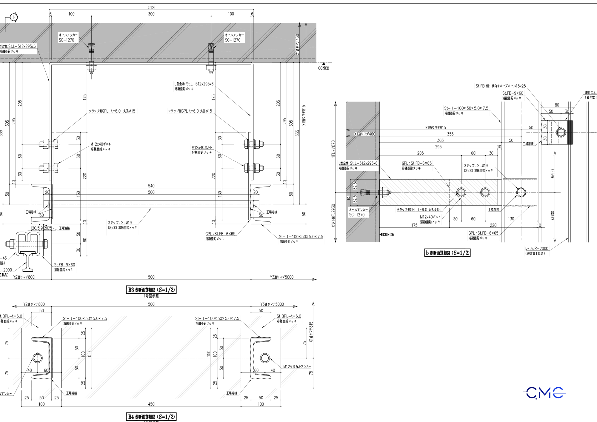
Suitable for highlighting the technical details of an item. This set of drawings helps the reader see the level of accuracy required in the design and construction process of steel ladders.
6. Handhold and Auxiliary Component Details
In some steel ladder systems, additional elements such as handholds, removable grips, or auxiliary steel components are required to improve usability and support maintenance work. Although these details may look small, they must be carefully shown in terms of size, position, bending radius, fixing method, and installation height.
If these auxiliary details are missing or unclear, they can easily be fabricated incorrectly or installed in the wrong position. This may reduce usability and create inconsistencies between the fabricated element and the actual site condition.
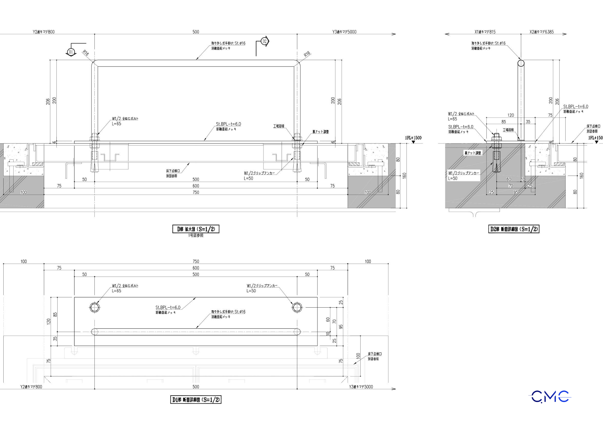
The drawings clearly show small but crucial details in practical use. This also demonstrates that the drawings not only serve the manufacturing process but also aim for safety and convenience during operation.
7. Controlling the Interface Between the Ladder and Surrounding Structures
In many projects, a steel ladder is not an isolated element. It is often connected directly to concrete walls, floor slabs, steel frames, beams, or other technical components. Therefore, the interface between the ladder and the surrounding structure must be carefully controlled.
The drawing should clarify the distance from the ladder to the wall, anchor positions in concrete, installation height relative to the floor, conditions around access openings, and possible conflicts with nearby structural or technical elements. These are common areas where mistakes can occur if the drawing is not detailed enough.
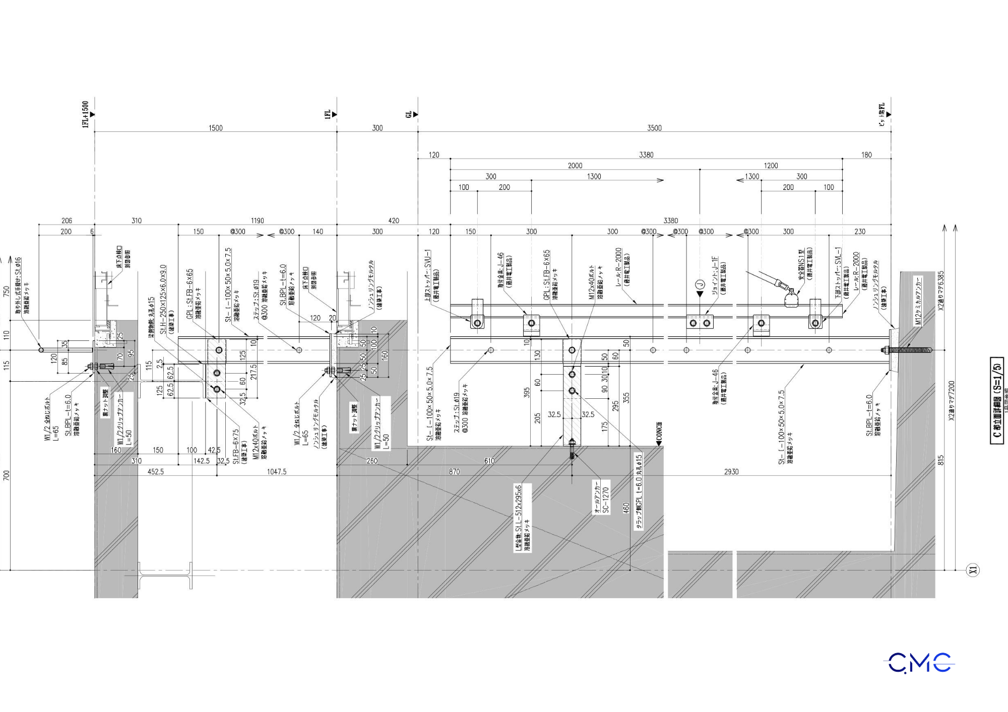
This clearly demonstrates the coordination between the ladder, base plate, anchoring, and existing structure. This type of detail helps the construction team easily visualize the installation conditions before going to the construction site.
8. The Value of Professional Steel Ladder Fabrication Drawings
A professional steel ladder fabrication and installation drawing set provides practical value throughout the project. First, it helps align information between the design team, fabrication workshop, and installation team. Second, it reduces production errors, rework, and unnecessary modification on site.
Detailed drawings also support material control, quantity checking, finishing requirements, and connection quality inspection. For steel components that require durability and safety, investing in accurate drawings from the beginning is an effective way to save time, cost, and effort during the entire construction process.
For CMC Architects Vietnam, each drawing is not just a technical document. It is a bridge between design requirements and real construction. A good drawing should help people understand correctly, fabricate correctly, install correctly, and inspect correctly.
9. CMC Architects Vietnam – Technical Drawing Services for Steel and Metalwork Items
CMC Architects Vietnam focuses on technical drawings, fabrication drawings, installation drawings, and AutoCAD 2D documentation for steel structures, architectural metalwork, and construction details.
Our work includes steel railings, handrails, steel stairs, steel ladders, steel frames, panels, louvers, door frames, and many other metalwork components. For every project, we aim to create drawings that are clear, accurate, coordinated, and practical for real fabrication and installation.
The strength of CMC Architects Vietnam lies in our systematic drawing organization. We clearly present plan views, elevations, sections, and connection details so that each drawing can be used effectively by fabricators, installers, and project teams.
Conclusion
Steel ladders are important technical components in many industrial, commercial, and building projects. To ensure accurate fabrication, safe installation, and smooth construction, the drawing set must be clear, detailed, and well-coordinated from the beginning.
Through this steel ladder drawing package, CMC Architects Vietnam continues to demonstrate a professional working approach: focusing on technical details, controlling drawing accuracy, and supporting real construction needs.
Are you looking for fabrication and installation drawings for steel ladders, steel stairs, railings, handrails, or other architectural metalwork items? Contact CMC Architects Vietnam to discuss a drawing solution that fits your project requirements.
CMC Architects Vietnam Accuracy in drawings, efficiency in construction.