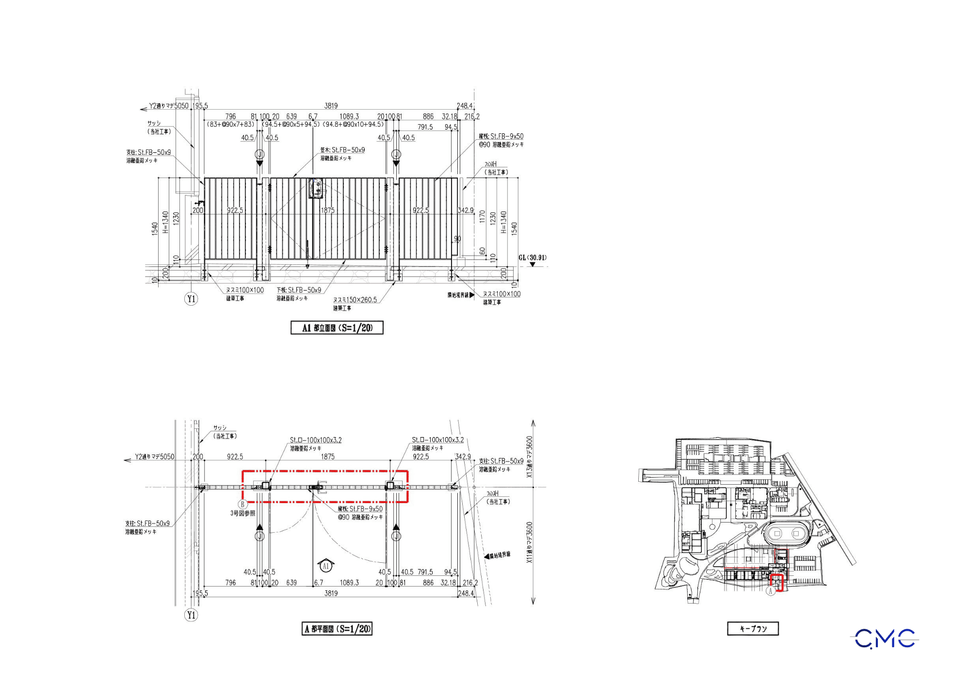
In modern office projects, safety is not only ensured by the main structural system but also by carefully designed details such as handrails, guardrails, partitions, protective frames, and safety barriers. These items may look simple at first glance, but they play an important role in controlling space, protecting users, and completing the professional appearance of the building.
With experience in developing technical drawings for steel, stainless steel, and architectural metalwork items, CMC Architects Vietnam provides fabrication and installation drawings for office safety barriers with a clear objective: accuracy, clarity, easy understanding, and practical support for production and on-site installation.
What Is an Office Safety Barrier?
An office safety barrier is a metalwork item used to divide areas, protect walkways, define working zones, or create safe boundaries in locations that require control. Depending on each project’s design requirements, the barrier can be made of stainless steel, painted steel, galvanized steel, glass combined with metal framing, or other finishing materials.
For this type of item, the technical drawing set must clearly show important information such as:
- Installation position on the floor plan.
- Length, height, and overall dimensions.
- Main frame, vertical members, and horizontal members.
- Base plates, bolts, and floor anchors.
- Connection details with the floor, wall, or surrounding structure.
- Material specifications, dimensions, and surface finishing requirements.
A clear drawing set helps the fabrication team understand exactly what needs to be produced and allows the installation team to work accurately according to the actual site conditions.
Why Are Fabrication and Installation Drawings Important?
During the construction of office metalwork items, unclear drawings, missing dimensions, or incomplete connection details can easily lead to problems such as incorrect installation positions, wrong frame dimensions, height deviations, missing accessories, or repeated adjustments on site.
Therefore, fabrication and installation drawings act as a “common technical language” between all related parties: design, fabrication, installation, inspection, and approval.
A well-prepared drawing set helps to:
- Reduce errors during fabrication.
- Shorten communication time between the technical office and the site team.
- Minimize additional modification costs.
- Help installers clearly understand the installation position and method.
- Ensure the final item is completed safely, accurately, and in line with the design intent.
Installation Layout – The Basis for Accurate Site Positioning
For safety barrier items, the layout drawing is one of the first drawings that must be checked carefully. It helps identify the exact installation area, the length of each barrier section, and the relationship with walls, columns, or functional areas within the office.
In the drawing set developed by CMC Architects Vietnam, the installation position, dimensions, and working scope are clearly presented, making it easier for the installation team to compare the drawing with actual site conditions.
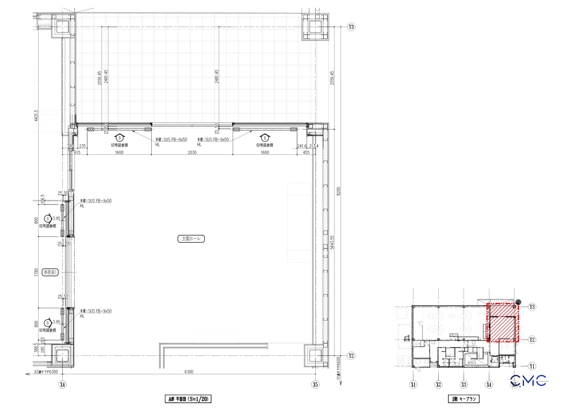
Image alt text: Office safety barrier installation layout drawing
Elevation and Section Drawings – Clarifying the Barrier Structure
If the layout drawing defines the location, the elevation and section drawings clarify the shape, height, structure, and connection method of the safety barrier. These drawings are essential for the fabrication team to manufacture the item with the correct dimensions and technical specifications.
The elevation and section drawings should clearly show:
- Overall height of the safety barrier.
- Spacing between vertical and horizontal members.
- Material specifications.
- Base plate positions.
- Fixing method to the floor.
- Bolt sizes, drilling holes, and fixing accessories.
- Finished level after installation.
With clear elevation and section drawings, workshop fabrication becomes more efficient, and the site team can also inspect the installation quality more easily.
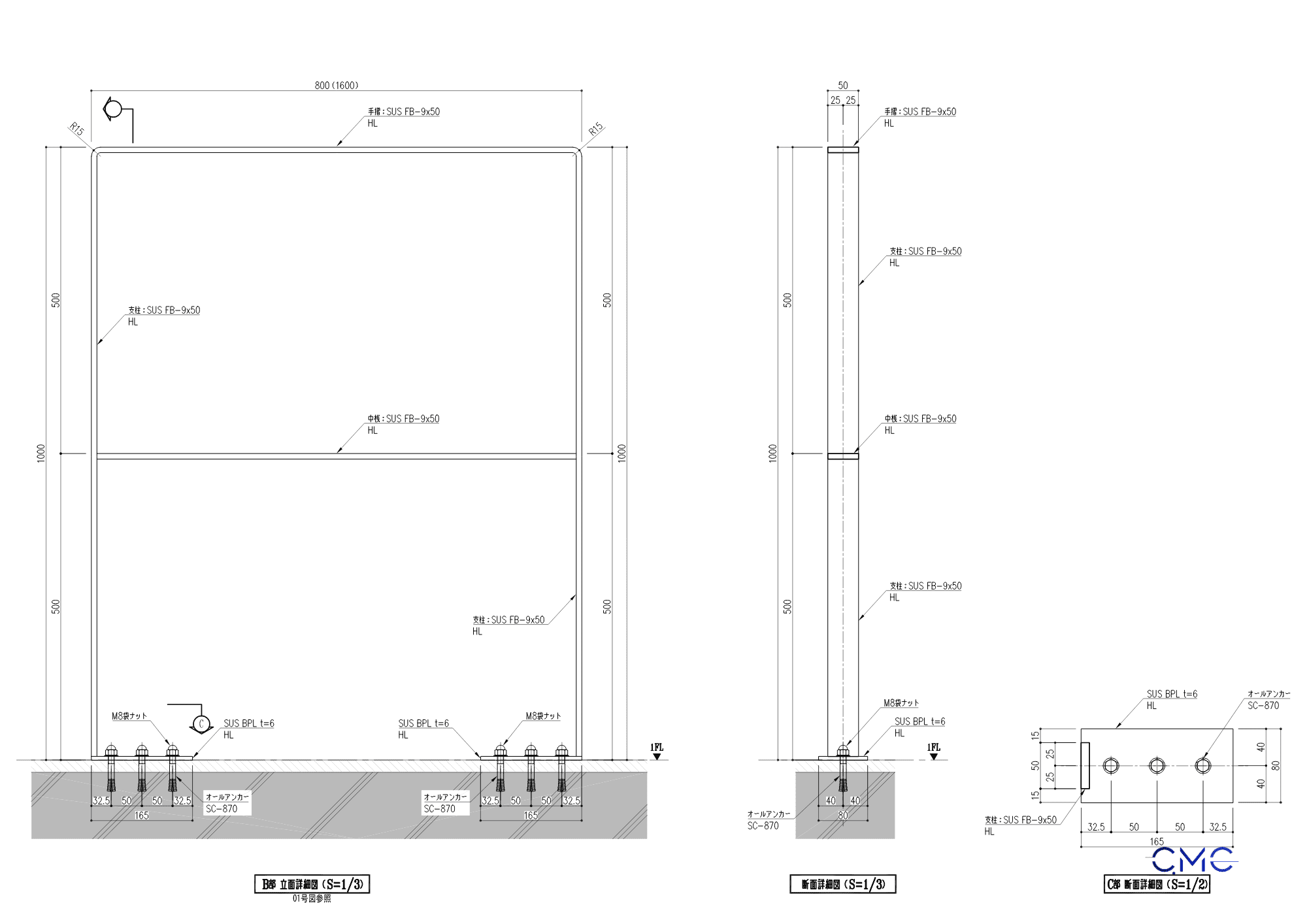
Image alt text: Elevation and section drawing of office safety barrier
Connection Details – The Key to Stability and Safety
For safety-related items, connection details must never be overlooked. A safety barrier can only perform well when the base connection, base plates, anchor bolts, and fixing method to the floor are clearly designed and shown in the drawings.
In installation drawings, connection details need to help the construction team understand:
- The size of the base plate.
- The type of anchor bolts to be used.
- Drilling positions and spacing between holes.
- The method of fixing the frame to the floor.
- Finishing requirements after installation.
When these details are fully presented, the project can avoid common issues such as incorrect installation, unstable fixing, vibration, or repeated adjustments after installation.
Clear Drawings Make Fabrication Easier and Installation More Accurate
A good technical drawing is not only clean in presentation but, more importantly, it must help people understand correctly and execute correctly. For office safety barrier items, the clearer the drawing is, the smoother the fabrication and installation process becomes.
CMC Architects Vietnam always focuses on developing drawings that are practical, easy to read, and easy to apply on site. From layout, elevation, and section drawings to connection details, every piece of information should be carefully checked to ensure consistency between design and construction.
This helps:
- The workshop easily prepare and fabricate the item.
- The installation team accurately identify installation positions.
- The client clearly understand the work scope.
- The inspection and approval process become more transparent.
- The final quality of the project be better controlled.
CMC Architects Vietnam – Technical Drawing Solutions for Architectural Metalwork Items
CMC Architects Vietnam specializes in technical drawings, fabrication drawings, and installation drawings for steel, stainless steel, aluminum, glass, and architectural metalwork items in construction projects.
Typical items developed by CMC Architects Vietnam include:
- Safety barriers.
- Guardrails and handrails.
- Steel staircases.
- Technical ladders.
- Panels, louvers, and steel boxes.
- Door frames and protective frames.
- Other metalwork details for construction projects.
With a working approach focused on accuracy, clarity, and professionalism, CMC Architects Vietnam aims to deliver drawing sets that are not only well-presented but also effective in real construction practice.
Conclusion
Office safety barriers are important items that help complete a safe, professional, and well-organized working environment. To ensure that these items are fabricated correctly, installed accurately, and completed with high quality, the fabrication and installation drawings must clearly show the layout, elevations, sections, and connection details.
With strong experience in AutoCAD 2D technical drawing development, CMC Architects Vietnam provides clear, practical, and reliable drawing solutions for each project.
Are you looking for technical drawings for safety barriers, handrails, guardrails, steel stairs, or architectural metalwork items? Contact CMC Architects Vietnam for accurate, professional, and construction-ready drawing solutions.
- 📞 Hotline: 0936361299
- 📧 Email: cmc.vn1013@gmail.com
- 🌐 Website: https://cmcarchitects.com/
- 📍 Address: 79A Xuan La, Tay Ho, Hanoi