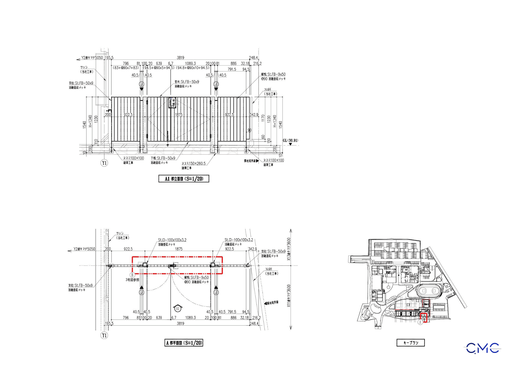
In modern construction projects, exhaust and ventilation duct systems must not only ensure stable operation but also achieve a neat, safe, and well-coordinated finish with the overall architectural design. In particular, the top panel of an exhaust / ventilation duct is a technical component that requires clear and detailed drawings to support fabrication, installation, inspection, and handover on site.
With experience in developing technical drawings using AutoCAD 2D, CMC Architects Vietnam provides detailed fabrication and installation drawing solutions that are clear, easy to read, easy to check, and practical for real construction work.
What Is the Top Panel of an Exhaust / Ventilation Duct?
The top panel of an exhaust or ventilation duct is a finishing component installed at the upper part of the air exhaust system. This element often plays an important role in protection, covering, airflow support, and creating a clean technical appearance for the surrounding area.
Although it may be considered a supporting detail, the top panel still needs to be accurately represented in the technical drawing set. If the dimensions, elevation, material, or connection details are unclear, the construction process may face errors, rework, or quality issues during installation.
A complete drawing set helps the fabrication and installation teams clearly understand:
- The installation position of the panel on the ventilation duct system.
- Overall dimensions and detailed dimensions.
- Supporting frames, brackets, fixing plates, or connection accessories.
- Elevation and installation direction.
- Materials used for each component.
- Key points to be checked before inspection and handover.
Why Does the Fabrication and Installation Drawing Need to Be Detailed?
In actual construction, technical panel components are often installed at high, narrow, or hidden locations, sometimes close to MEP systems or surrounding structural elements. This requires a high level of accuracy during fabrication and installation.
If the drawing does not provide enough information, the site team may need additional time to verify, adjust, or solve unexpected issues on site.
A clear fabrication and installation drawing helps:
- Reduce dimensional errors during panel fabrication.
- Support accurate installation on site.
- Control the connection between the panel, supporting frame, and surrounding structure.
- Ensure the panel shape follows the design requirements.
- Make inspection and handover faster and more efficient.
- Minimize additional costs caused by modification or rework.
This is why CMC Architects Vietnam always focuses on clarity, consistency, and practical usability in every technical drawing package.
Plan Drawing – The Basis for Defining the Panel Position
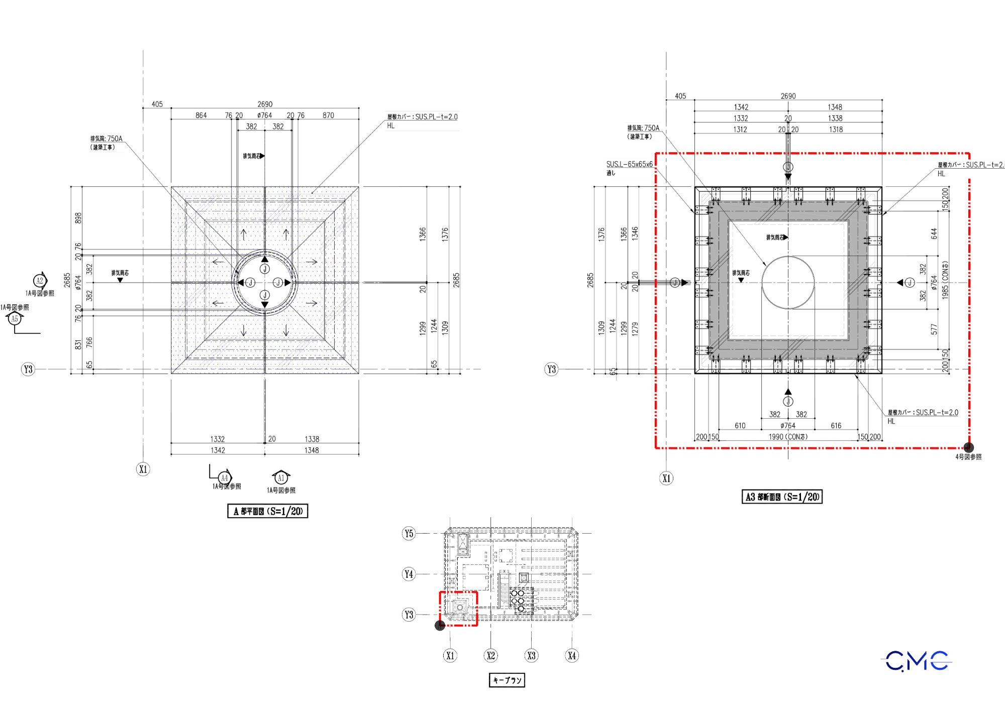
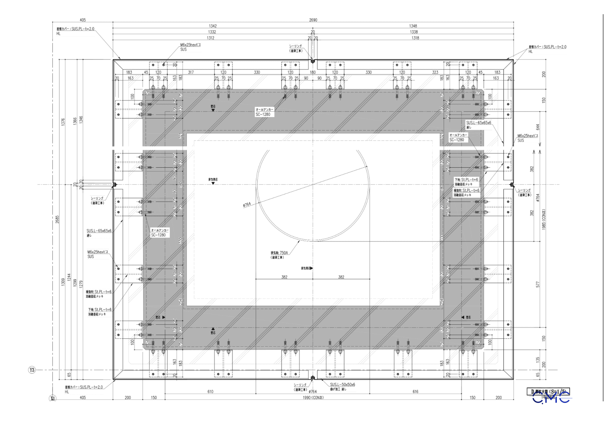
The plan drawing is the first important part of the drawing set for the top panel of an exhaust / ventilation duct. Through the plan, readers can identify the panel position within the overall project, horizontal dimensions, duct location, airflow direction, and connection range with surrounding components.
In the drawing, information such as grid lines, overall dimensions, duct position, installation direction, and the panel layout must be clearly shown to avoid misunderstanding during fabrication and installation.
Elevation Drawing – Showing Shape and Installation Height
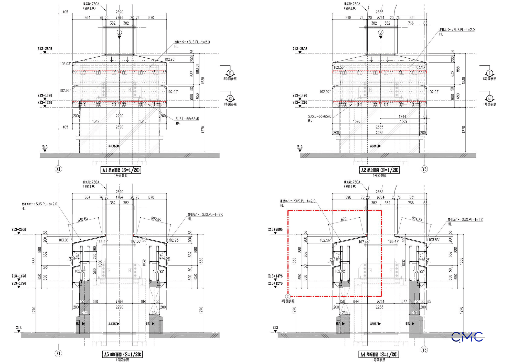
The elevation drawing helps clarify the external shape of the panel, installation height, slope, elevation, and relationship between the panel and the upper exhaust duct. This is an important part of the drawing set because it allows the fabrication team to understand the final appearance and actual proportions of the component.
For the top panel of an exhaust / ventilation duct, the elevation drawing should clearly show:
- Overall panel height.
- Installation elevation in relation to the floor or surrounding structure.
- Shape of the cover or surrounding panel.
- Position of the ventilation duct.
- Panel edges, trims, joints, or connection lines.
- Material and surface finishing notes, if required.
Section Drawing – Clarifying Structure and Installation Method
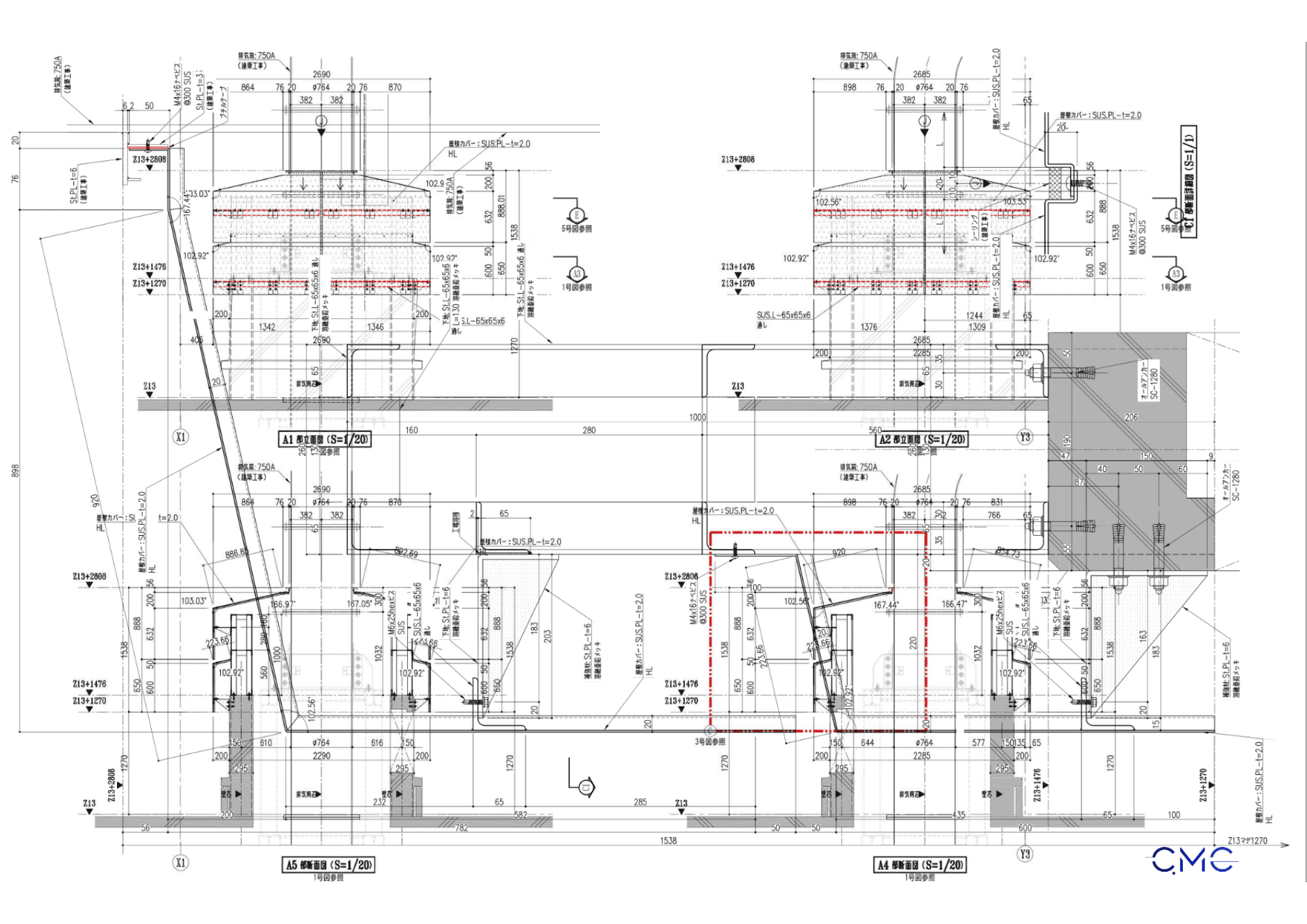
The section drawing helps readers understand the internal structure of the component. If the plan drawing shows where the panel is located and the elevation drawing shows what it looks like, the section drawing explains how the panel is built and installed.
For this item, the section drawing should show:
- Panel thickness.
- Cover layer or top cap structure.
- Internal supporting frame.
- Connection points to steel or concrete structure.
- Technical gaps.
- Airflow direction and operating space.
- Fixing, anti-vibration, or alignment details, if any.
When the section drawing is developed clearly, the installation team can check each structural layer before installation, reducing the risk of differences between the drawing and actual construction.
Structural Details – The Key to Accurate Fabrication
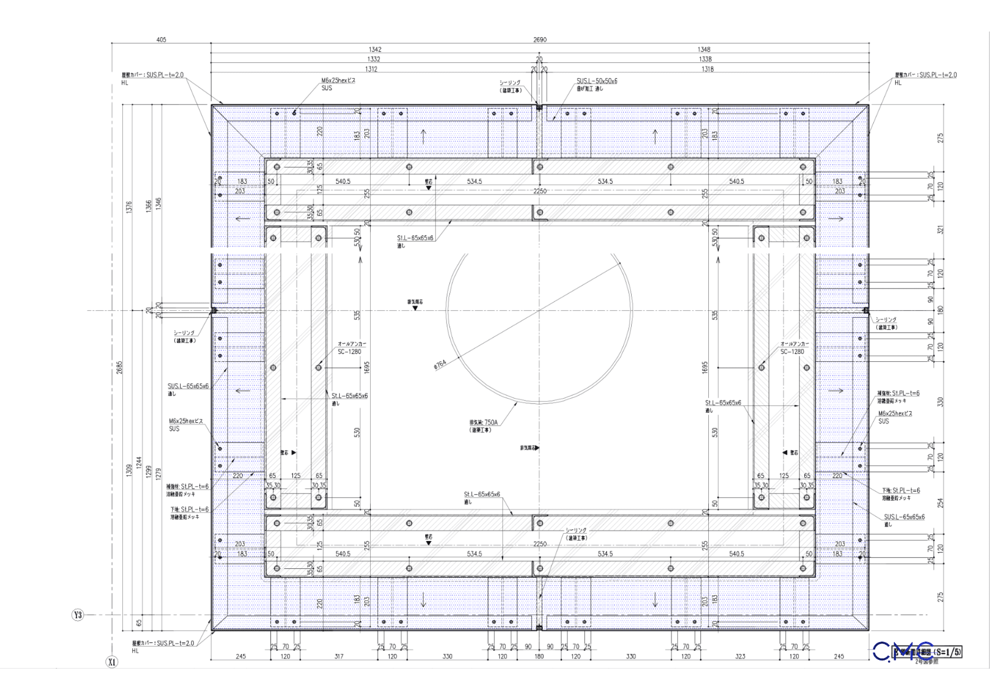
For fabrication drawings, structural details are especially important. These details provide the basis for the workshop to determine the correct dimensions of each panel piece, fixing hole positions, trims, supporting frames, plates, and connection points.
A good structural detail should help the reader answer the following questions:
- How is the panel divided into different parts?
- What are the dimensions of each part?
- Where are the fixing holes located?
- How is the supporting frame arranged?
- How is the panel connected to the duct and surrounding structure?
- Are there requirements for surface finishing, rust protection, or waterproofing?
At CMC Architects Vietnam, every drawing detail is prepared to be clear and practical, allowing the fabrication team to produce the component correctly from the beginning and reduce modifications after delivery to site.
Connection Details – Controlling Quality During Installation
Connection details help ensure that the panel is installed firmly, accurately, and safely during operation. For technical components such as the top panel of an exhaust / ventilation duct, the connection method must be clearly shown to prevent incorrect installation direction, missing bolts, incorrect spacing, or insufficient stability.
Connection details should include:
- Bolt, screw, or fixing accessory positions.
- Spacing between connection points.
- Dimensions of fixing plates or supporting members.
- Connection method between the panel and steel frame.
- Joint position between the panel and ventilation duct.
- Edge treatment, trims, gaps, or waterproofing requirements, if any.
With detailed drawings, the installation team can check every position before assembly, making the inspection and handover process smoother and more transparent.
The Value of Technical Drawings from CMC Architects Vietnam
A high-quality technical drawing set does more than help the construction team build correctly. It also improves coordination between designers, fabricators, and site installation teams. All parties need a drawing package that is clear, complete, and easy to check.
CMC Architects Vietnam focuses on developing AutoCAD 2D technical drawings for steel components, panels, louvers, handrails, railings, ladders, steel frames, and architectural metal details. For every project, we aim for three core values: accuracy, clarity, and practical constructability.
Drawings prepared by CMC Architects Vietnam help:
- Standardize technical information before fabrication.
- Reduce errors during production.
- Support faster and more accurate site installation.
- Improve the professionalism of technical documentation.
- Support inspection and handover effectively.
- Contribute to better overall construction quality.
Clear Drawings Are the Foundation of Accurate Construction
In technical construction work, accuracy does not come from a single detail. It comes from the consistency of the entire drawing set. The plan must show the correct position, the elevation must clearly show the shape, the section must explain the structure, and the connection details must provide enough information for installation.
For the top panel of an exhaust / ventilation duct, the clearer the drawing is, the smoother the fabrication and installation process will be. This is an important factor in ensuring long-term safety, aesthetics, and operational efficiency for the project.
Conclusion
The fabrication and installation drawing for the top panel of an exhaust / ventilation duct is an important document for controlling quality from fabrication to actual site installation. A complete drawing set with plan, elevation, section, and connection details helps reduce errors, save time, and improve the professionalism of the project.
With experience in technical drawings for steel and architectural metal components, CMC Architects Vietnam is ready to support projects that require accuracy, clarity, and efficiency in every detail.
Are you looking for fabrication and installation drawings for panels, louvers, exhaust duct components, ladders, handrails, railings, or architectural metal works? Contact CMC Architects Vietnam for a suitable technical drawing solution for your project.
- 📞 Hotline: 0936361299
- 📧 Email: cmc.vn1013@gmail.com
- 🌐 Website: https://cmcarchitects.com/
- 📍 Address: 79A Xuan La, Tay Ho, Hanoi