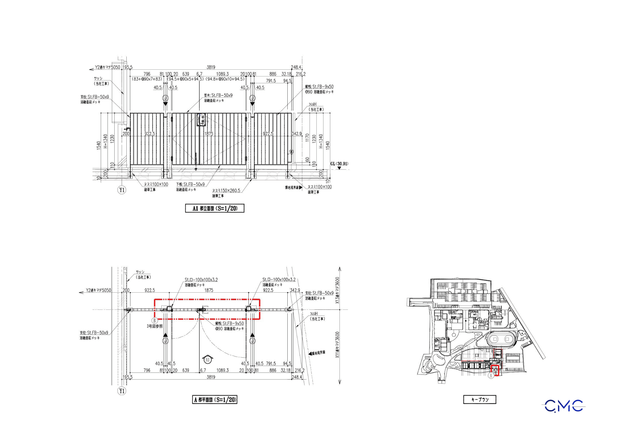
In public buildings such as children’s centers, schools, community facilities, or spaces designed for young users, every architectural detail must be carefully developed. Each component needs to be visually appropriate, safe, durable, accurate for construction, and suitable for real-life use.
One detail that may seem small but plays an important role is the three-sided frame. This component supports the finishing of door openings, wall openings, entrances, or transition areas between different spaces. Without clear technical drawings, fabrication and installation can easily face issues such as dimensional errors, incorrect levels, misaligned fixing positions, or inconsistent finishing details.
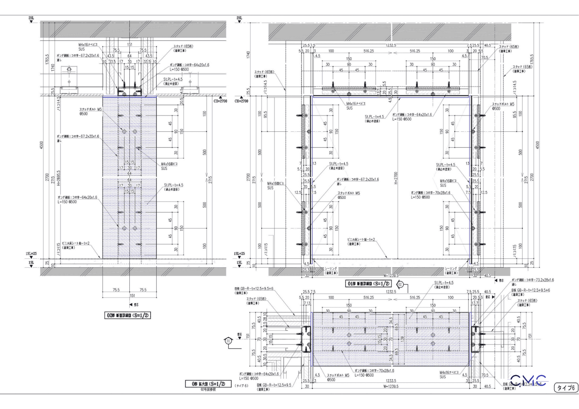
For the project Fabrication and Installation Drawings for Three-Sided Frames for a Children’s Center, CMC Architects Vietnam developed a detailed technical drawing package that includes key information such as general plans, detailed plans, elevations, sections, connection details, component dimensions, materials, and installation methods.
What Is a Three-Sided Frame and Why Does It Need Detailed Drawings?
A three-sided frame is a frame system installed around three sides of an opening, usually consisting of two vertical sides and one horizontal top side. This type of frame is commonly used around doors, corridors, functional rooms, restrooms, halls, support rooms, or areas where wall edges need to be finished and protected.
In buildings used by children, the frame is not only a finishing element but also contributes to safety during daily use. Therefore, the technical drawings must clearly show:
- The installation position of each frame type.
- The height, width, and depth of the frame.
- The materials used for each component.
- Connection details with walls, floors, ceilings, or surrounding structures.
- Installation levels and finishing positions.
- Fabrication, installation, and surface finishing methods.
The clearer the drawing, the smoother the production and installation process. This also helps reduce errors, shorten on-site adjustment time, and improve the final finishing quality.
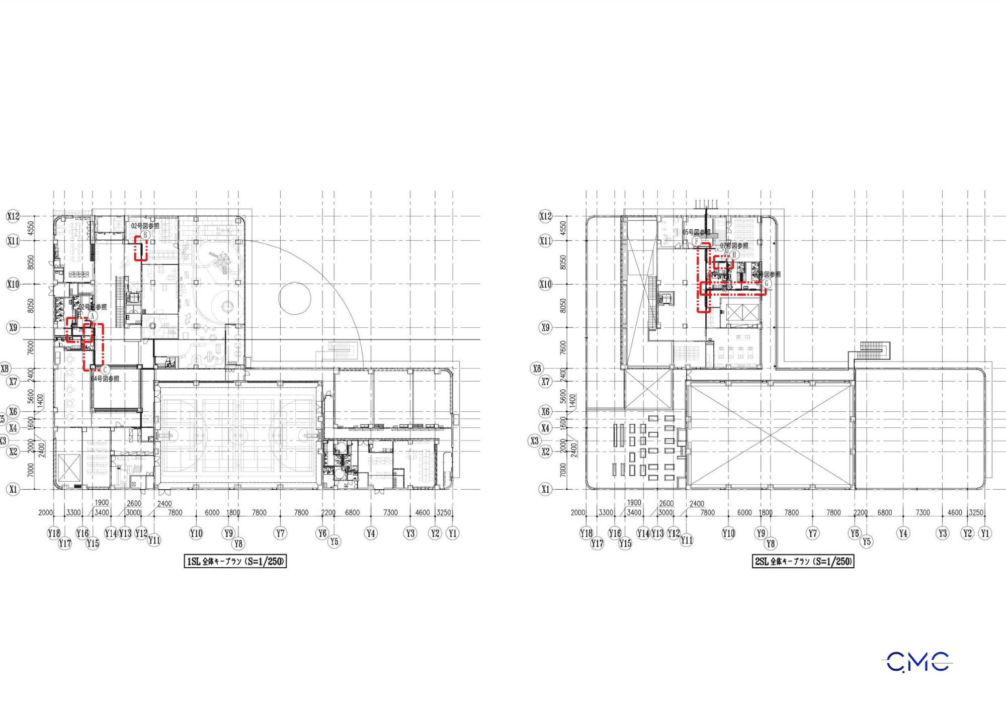
General Plan – Defining the Correct Installation Locations
In a three-sided frame drawing package, the general plan is one of the most important parts. It helps identify the exact installation location of each frame within the building and shows how the frame relates to the surrounding architectural space.
In this project, the plan drawings clearly indicate the floors, functional areas, frame installation positions, and reference symbols linked to detail drawings. This provides a reliable basis for the construction team to locate each frame accurately before installation and avoid confusion between different frame types with different sizes or configurations.
Detailed Plan – Controlling Dimensions for Each Area
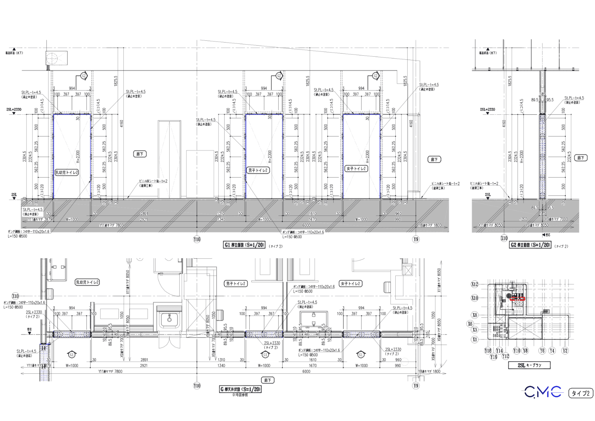
After identifying the overall positions, the detailed plan clarifies the dimensions of each installation area. This part helps the construction team understand where each frame is located, what its size is, and how it connects with surrounding walls or partitions.
The drawings show dimensions based on grid lines, levels, and detailed reference symbols. As a result, the fabrication workshop can produce components with the correct dimensions, while the site team can recheck the existing site conditions before installation.
For steel and architectural metal components, even a small dimensional error in the plan can affect the entire installation process. That is why clear drawing presentation is essential.
 .
.
Elevation Drawings – Showing the Shape and Levels of the Frame
Elevation drawings help viewers understand the appearance of the frame when seen from the front. For three-sided frames, elevations typically show the frame height, opening width, vertical frame members, top frame member, finishing position, and related levels.
This is an important basis for checking consistency between the technical drawings and the overall architectural design. If the elevation is not clearly shown, the installed frame may be placed at the wrong level, shifted from its intended position, or not aligned with surrounding finishes.
In this drawing set, elevations are developed for different frame types, making it easier for the installation team to identify and apply the correct drawing to each location.

Section Drawings – Clarifying Structure and Connection Methods
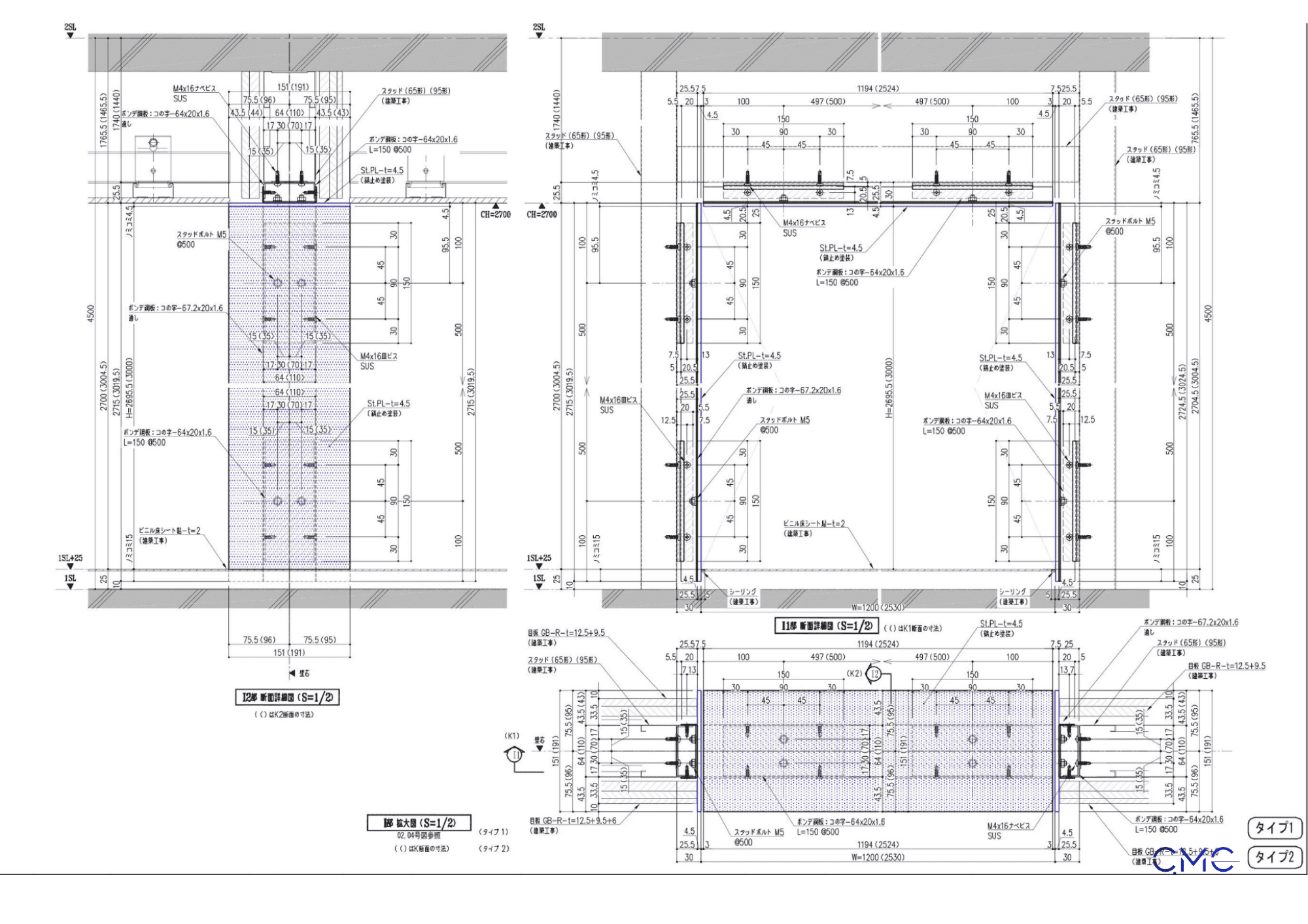
If the plan shows the location and the elevation shows the appearance, the section drawing explains the actual structure of the frame. This part presents important information such as steel thickness, finishing layers, frame configuration, connection spacing, and how the frame meets the wall, floor, or ceiling.
For three-sided frames, section drawings help both the workshop and the site team understand exactly how each component is formed. Details such as steel plates, finishing panels, anchors, screws, bolts, or finishing gaps must be shown clearly to ensure that fabricated products can be installed correctly on site.
Connection Details – Key to Accurate Installation
A high-quality fabrication and installation drawing package cannot be complete without connection details. For three-sided frames, connection points are usually located at the vertical members, top member, wall junctions, anchor points, screw positions, and fixing locations.
These details help reduce common construction errors such as:
- The frame being misaligned with the opening.
- Fabricated dimensions not matching actual site conditions.
- Inconsistent screw or fixing positions.
- The installed frame not achieving the required stability.
- Finishing surfaces not matching the surrounding architecture.
With detailed drawings, the construction team can check every step before installation, improving both accuracy and final quality.
Multiple Frame Types – Suitable for Different Installation Locations
In real construction projects, not every location uses the same frame type. Depending on the area, opening height, opening width, connection conditions, and finishing requirements, each frame type may have its own structure and dimensions.
The drawing package developed by CMC Architects Vietnam shows multiple frame types, helping the production and installation process become clearer and more organized. Separating each frame type by symbol, plan, elevation, and section helps reduce confusion during on-site work.
This is especially important in projects with many functional areas, multiple floors, and several similar installation locations.
The Value of Fabrication and Installation Drawings by CMC Architects Vietnam
CMC Architects Vietnam always focuses on clarity, accuracy, and practical application in every technical drawing package. For steel and architectural metal components such as frames, railings, handrails, steel stairs, ladders, panels, louvers, and door frames, drawings must not only be well presented but also easy to read, easy to fabricate, and practical for construction.
A good drawing package helps:
- Project owners control technical documentation more effectively.
- Fabrication workshops understand production requirements clearly.
- Site teams reduce installation errors.
- Inspection and handover processes become smoother.
- The final project achieves consistent and professional finishing quality.
With experience in developing AutoCAD 2D drawings for steel and architectural metal items, CMC Architects Vietnam aims to deliver technical drawing packages that are clear, practical, and valuable for real project execution.
Conclusion
The fabrication and installation drawings for three-sided frames for the Children’s Center demonstrate the important role of technical documentation in construction. When plans, elevations, sections, and connection details are fully presented, fabrication and installation can be carried out with greater accuracy, safety, and efficiency.
For CMC Architects Vietnam, every drawing is not only a technical document but also a bridge between design, production, and on-site construction. Clarity in drawings is the foundation for professional, durable, and reliable projects.
Are you looking for fabrication drawings, installation drawings, or technical drawings for steel components, architectural metalwork, three-sided frames, railings, handrails, steel stairs, or panels? Contact CMC Architects Vietnam to receive a suitable drawing solution for your project.
- 📞 Hotline: 0936361299
- 📧 Email: cmc.vn1013@gmail.com
- 🌐 Website: https://cmcarchitects.com/
- 📍 Address: 79A Xuan La, Tay Ho, Hanoi