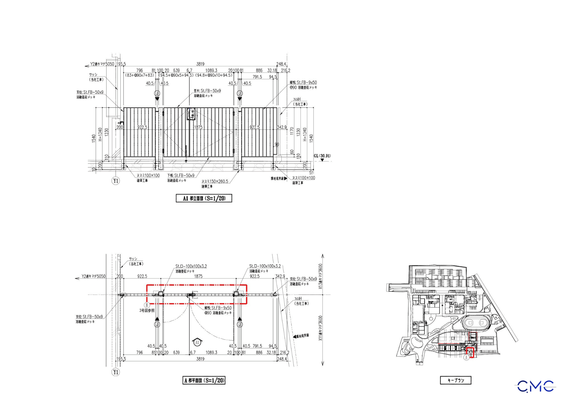
In residential buildings, schools, hospitals, offices, and public facilities, corridors are not only circulation areas. They are also important spaces that require careful consideration of safety, usability, and long-term durability. One detail that may look simple but plays a very important role is the wall-mounted handrail for corridors.
For this type of item, a technical drawing does not only show where the handrail will be installed. It must also clearly indicate the mounting height, dimensions, fixing points, end conditions, bracket spacing, and connection details related to walls, doors, stairs, and transition areas.
At CMC Architects Vietnam, each set of wall-mounted handrail drawings is developed with a focus on clarity, accuracy, and practical construction, helping fabrication and installation teams understand the design correctly and execute the work efficiently.
1. What Is a Wall-Mounted Corridor Handrail?
A wall-mounted handrail is a handrail system installed directly or indirectly onto a wall using brackets, fixing plates, bolts, anchors, or specialized connection components. This type of handrail is commonly used along corridors, stairways, common walkways, and other areas where users need additional support while moving.
In real construction projects, a wall-mounted handrail must meet several requirements at the same time. It needs to be positioned correctly according to the architectural plan, installed at the proper height, arranged with consistent spacing, securely fixed to the wall or structural surface, and finished safely at the start and end points without interfering with doors, corners, columns, or technical boxes.
For that reason, a handrail construction drawing cannot stop at showing only the overall shape. It needs to present each segment, each fixing point, and each special condition clearly to reduce mistakes during fabrication and installation.
2. The Role of Technical Drawings in Corridor Handrail Design
If a corridor handrail system is not developed with complete technical drawings, many issues may occur during construction. The handrail may be installed in the wrong location, at an incorrect height, misaligned with the wall, interfering with doors, missing end details, or requiring adjustments on site.
With a clear technical drawing set, all parties involved can easily control the handrail installation scope for each floor, the handrail position based on grids and floor plans, the height from finished floor level, the length of each segment, bracket locations, anchor points, and wall connection details.
This is the key foundation that makes the drawing not only well-presented, but also highly practical for fabrication and on-site installation.
3. General Floor Plan – Defining the Handrail Installation Scope
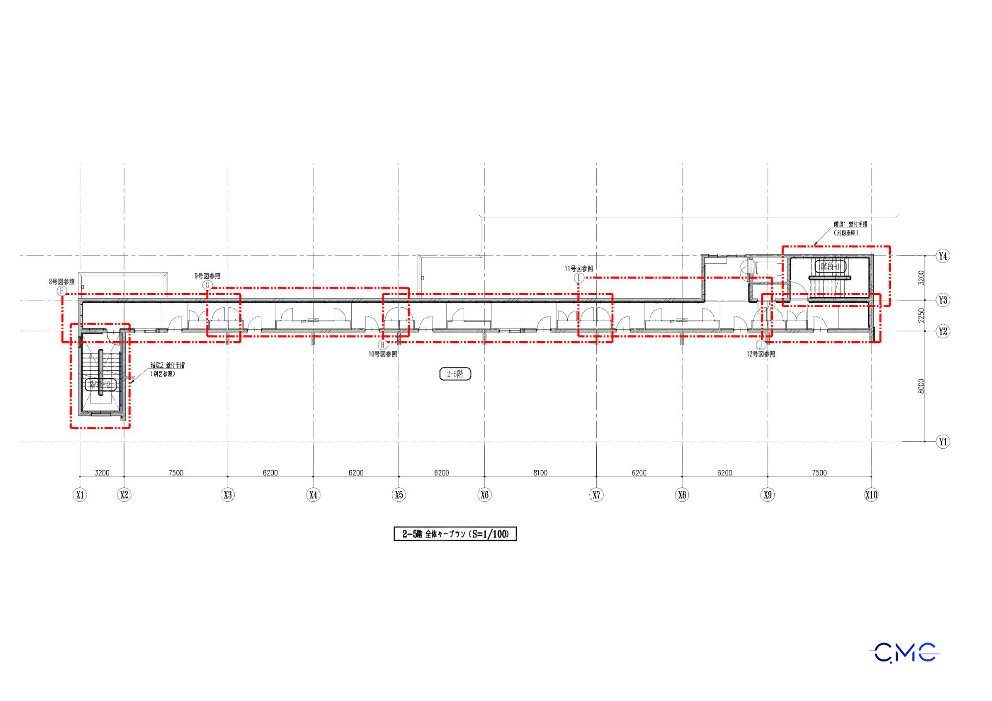
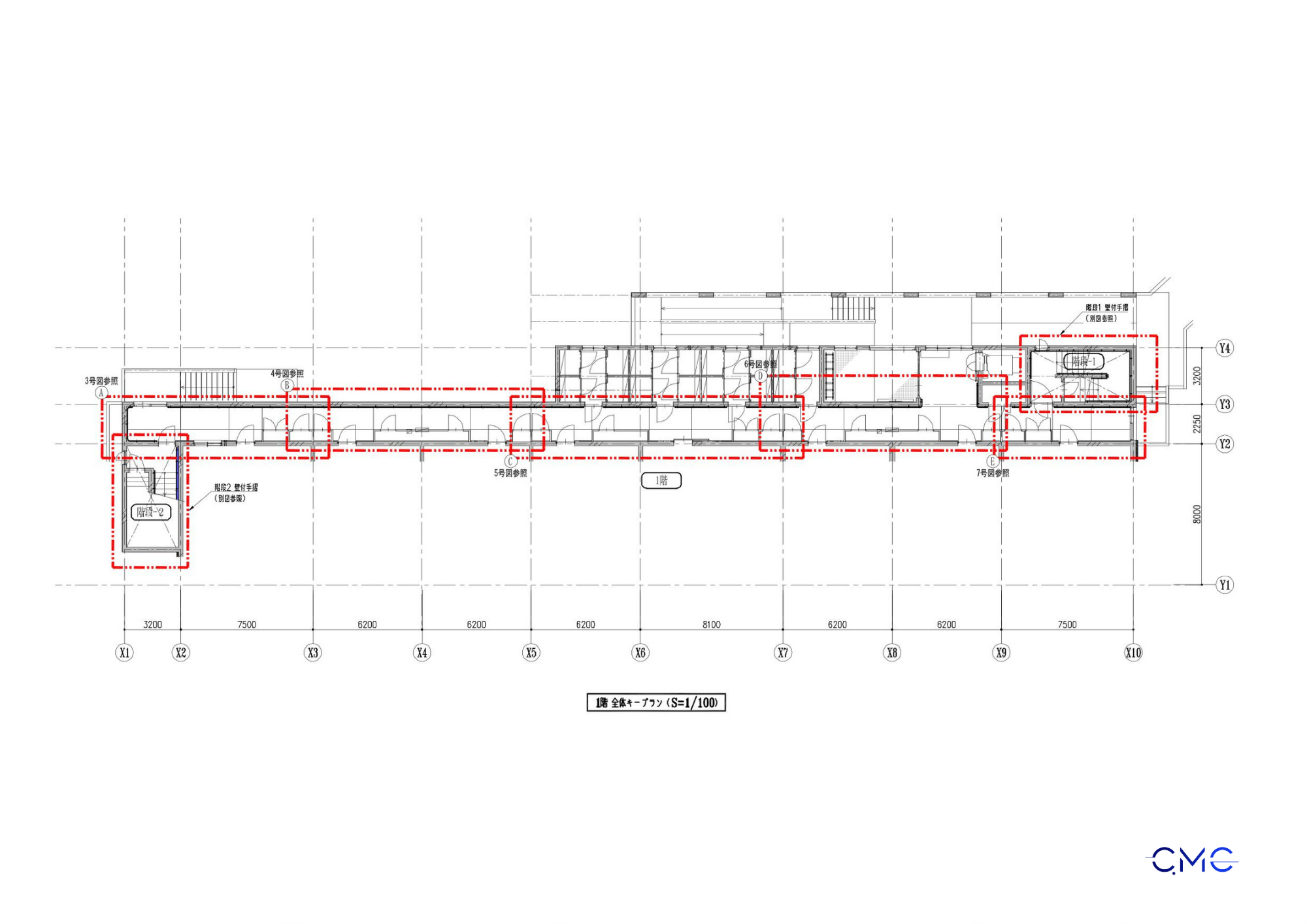
In a wall-mounted corridor handrail drawing set, the general floor plan helps viewers quickly understand where the handrail is located, which corridor areas it covers, and how it relates to surrounding spaces.
In the floor plan drawings, the handrail areas are clearly marked by floor, allowing the construction team to understand the installation scope before moving into more detailed drawings. This is an important step to avoid confusion between different floors, grid lines, and corridor zones with similar layouts.
For projects with long corridors, multiple doors, several turning points, or repeated floor layouts, the general floor plan helps control the handrail system in a more systematic way.
4. Elevation Drawings – Showing Length, Height, and Handrail Arrangement
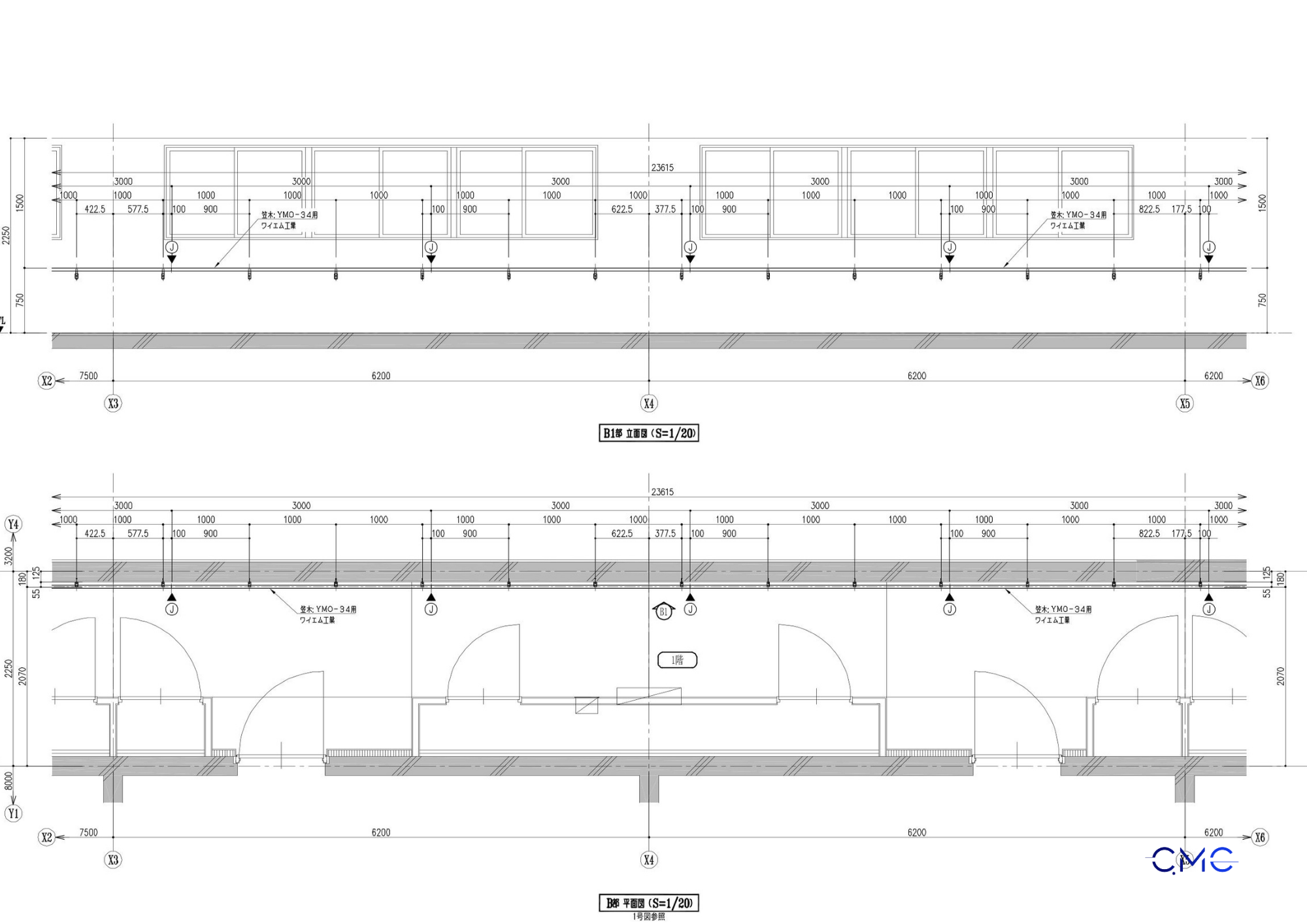
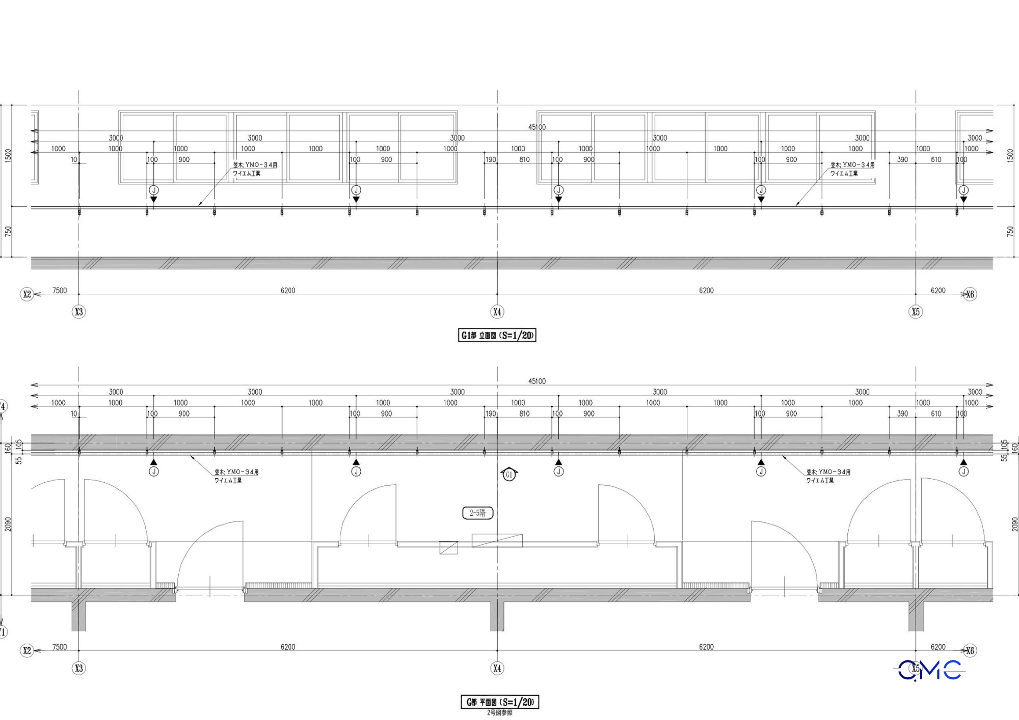
If the floor plan defines the horizontal position, the handrail elevation drawing clarifies the shape, length, installation height, and relationship between the handrail and surrounding architectural elements such as floors, walls, doors, windows, and corridor openings.
This is a very important part of the drawing set because corridor handrails must be continuous, comfortable to use, and suitable for the actual height requirements of the building. Long handrail segments need to be divided logically, with clear indications of bracket locations, connection points, end points, and special conditions.
A well-developed elevation drawing helps the construction team understand exactly where the handrail starts and ends, the length of each handrail segment, the mounting height from the finished floor level, the spacing between support brackets, and the handrail arrangement when passing doors, walls, corners, or stair areas.Alt
For floors with similar layouts, clearly developed elevation drawings help maintain consistency between areas, support faster installation, and reduce mistakes during the construction process.
5. Sections and Connection Details – Key Factors for Construction Quality
For wall-mounted handrails, connection details are essential. These details show how the handrail is fixed to the wall, what type of bracket is used, how far the handrail is offset from the wall, where anchors are located, and how the handrail ends are treated.
Typical detail drawings include handrail section details, wall bracket details, end cap details, curved handrail sections, corner conditions, transition details, spacing from the wall surface, and connection details using anchors, screws, bolts, or fixing plates.
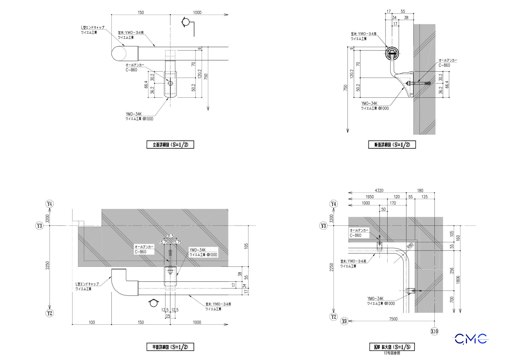
Caption: Detailed drawing of wall-mounted handrail connections, handrail ends, and support brackets.
These detail drawings help fabrication and installation teams understand the actual construction method more clearly, reducing the risk of rework on site. When technical details are fully presented, production, inspection, and acceptance also become more efficient.
6. Controlling Special Locations Along the Corridor
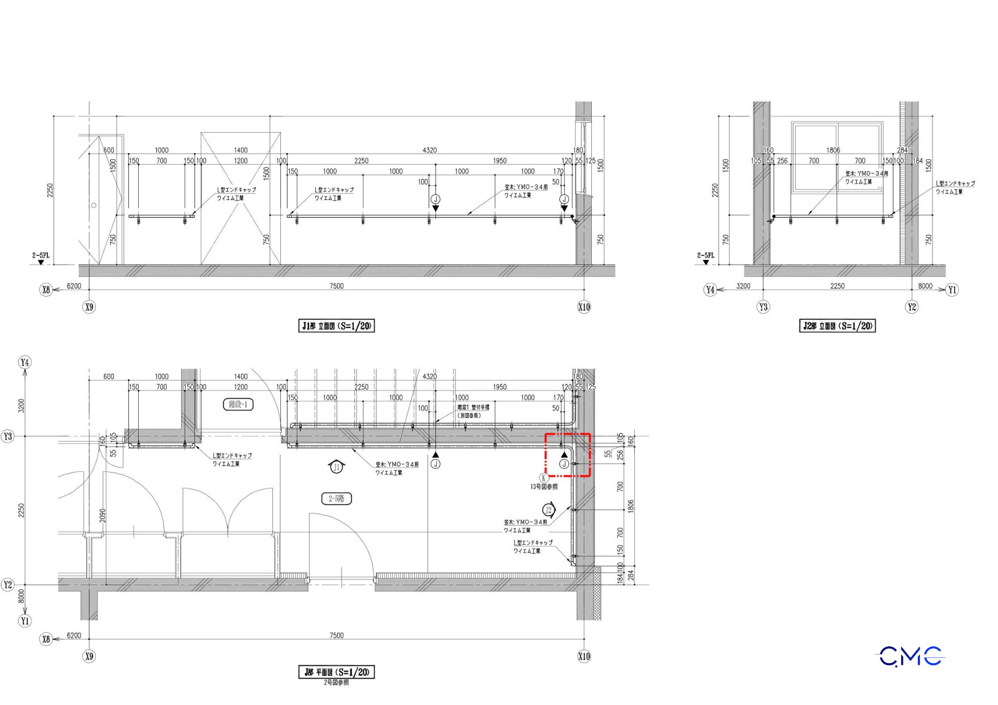
In real construction, wall-mounted handrails are not always installed in one continuous straight line. The handrail system may pass through many special locations such as door openings, wall corners, turning points, secondary staircases, corridor intersections, or end points near walls.
These areas need to be shown clearly through enlarged details or combined plan and elevation drawings so that the construction team can understand the correct installation method.
Caption: Detail drawing showing handrail positions at doors, wall corners, and corridor transition areas.
In addition, overall drawing sheets help viewers observe the full handrail system within the same area. This type of drawing is useful for reviewing the complete layout before fabrication or installation begins.
7. Key Strengths of the Handrail Drawings Designed by CMC Architects Vietnam
In this drawing set, CMC Architects Vietnam focuses on clarity, consistency, and practical application. The drawings do not only show the general handrail location, but also develop each technical detail to support more accurate construction.
Some notable strengths of this drawing set include:
- Clear handrail installation scope shown on each floor plan.
- Elevation drawings showing length, height, and installation position.
- Separate control of handrail segments along corridors, doors, wall corners, and stair areas.
- Enlarged details for handrail end conditions and wall-mounted connections.
- Technical information arranged in a systematic and easy-to-read format.
- Drawings that support fabrication, installation, and on-site inspection.
Caption: Corridor handrail elevation drawings with clear dimensions to support accurate installation.
For architectural metalwork items such as handrails, railings, steel stairs, louvers, panels, and steel frames, drawing accuracy is always an important factor in reducing errors and optimizing construction progress.
8. Why Should Wall-Mounted Handrail Drawings Be Developed from the Beginning?
Many people may consider handrails to be a small item. However, in actual construction, if the technical drawings are not complete, this item can easily create problems during installation. A small error in bracket position, handrail height, or distance from the wall can affect both appearance and usability.
Developing technical drawings from the beginning helps reduce fabrication errors, minimize on-site adjustments, simplify quantity and scope checking, maintain consistency between floors, improve the professionalism of construction documents, and support a clearer inspection process.
For CMC Architects Vietnam, a good drawing is not only a drawing with sufficient lines and dimensions. It must also help construction teams understand the design correctly, build accurately, and control quality effectively.
9. CMC Architects Vietnam – Professional Technical Drawing Design Services
CMC Architects Vietnam specializes in technical drawings, construction drawings, fabrication drawings, and AutoCAD 2D drawing development for architectural, structural steel, and architectural metalwork items.
With experience in developing drawings for railings, handrails, steel stairs, ladders, panels, louvers, door frames, and other metal details, CMC Architects Vietnam aims to create drawing sets that are clear, accurate, and highly practical for real construction.
Each drawing is developed with attention to dimensional accuracy, consistency between views, easy-to-understand presentation, clear connection details, and strong support for fabrication and on-site installation.
Conclusion
Wall-mounted handrails for corridors are important elements that contribute to safety, comfort, and overall building completion. To ensure accurate installation, the technical drawing set must clearly show the floor plan, elevation, section, and connection details.
Through this drawing set, CMC Architects Vietnam continues to demonstrate its professional working approach: clear documentation, precise detailing, and practical support for construction.
Are you looking for technical drawings for handrails, railings, steel stairs, or architectural metalwork items? Contact CMC Architects Vietnam for drawing solutions tailored to your project.
CMC Architects Vietnam – Accuracy in drawings, efficiency in construction.