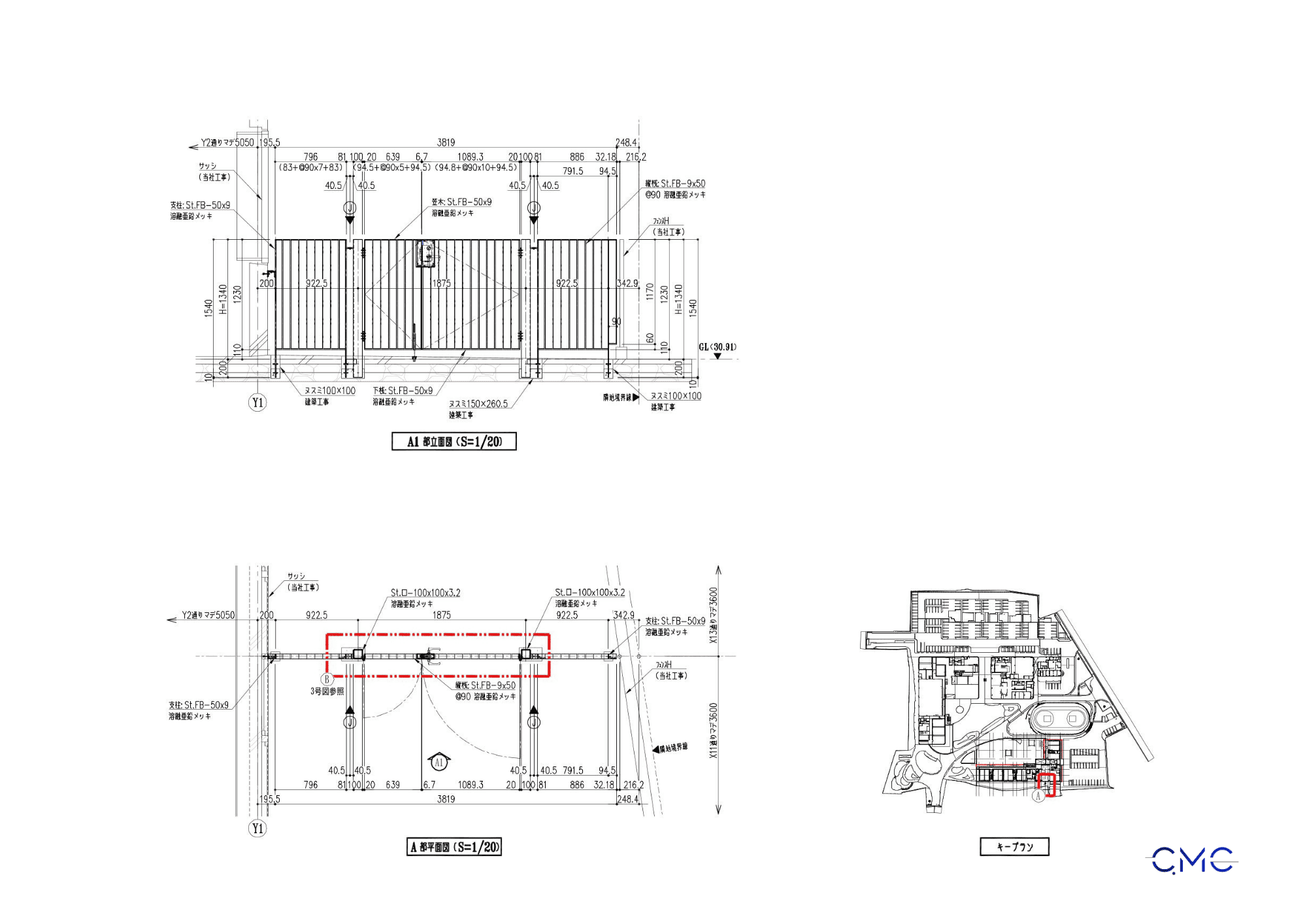
In residential buildings, balconies are not only spaces for natural light, ventilation, and architectural expression, but also areas that require a high level of safety, durability, and aesthetic consistency. For that reason, the balcony railing system must be designed, fabricated, and installed based on a clear, complete, and practical technical drawing set.
For the scope of aluminum balcony railings, construction drawings play an important role in controlling installation positions, overall dimensions, heights, spacing between vertical bars, connection details, fixing methods, and consistency between floors.
At CMC Architects Vietnam, we focus on developing technical drawings that are clear, accurate, and practical for real construction conditions. Each drawing does not only help the construction team understand the design correctly, but also supports fabrication, installation, inspection, and project handover more effectively.
Aluminum Balcony Railings – A Small Element with a Big Impact on Construction Quality
Balcony railings are frequently visible on the exterior facade of a building. When properly developed and installed, they help the building appear cleaner, more consistent, and more modern. However, if the drawings are unclear, problems such as incorrect installation positions, inconsistent heights, uneven bar spacing, weak connections, or poor coordination with the actual structure may occur during construction.
Especially for aluminum railings, it is important to control dimensions, gaps, post locations, vertical bars, horizontal members, and connections to walls or floor structures. The more complete the drawing set is, the smoother the fabrication and installation process becomes, reducing the need for on-site corrections.
A professional aluminum balcony railing drawing set should clearly answer key questions such as:
Where will the railings be installed on the plan?
What are the dimensions of each railing section?
How are the height and level controlled?
How are posts, vertical bars, and connection points arranged?
How are anchors, screws, brackets, and fixing details connected to walls or floors?
Are repeated railing sections between floors consistent?
When these details are clearly shown, the construction team can work more accurately, reduce mistakes, and improve the overall finishing quality of the project.
Overall Plan Drawing – Defining the Installation Positions of Balcony Railings
The overall plan drawing is the first important part of the drawing set. It helps define the locations of balcony railing installation by floor, grid line, and building area.
For aluminum balcony railings, the overall plan allows the technical team to quickly identify the construction scope, the number of railing locations, and the relationship between the railings and surrounding spaces such as apartment units, corridors, walls, and structural elements.
This is an important foundation before developing more detailed drawings such as elevations, sections, and connection details.
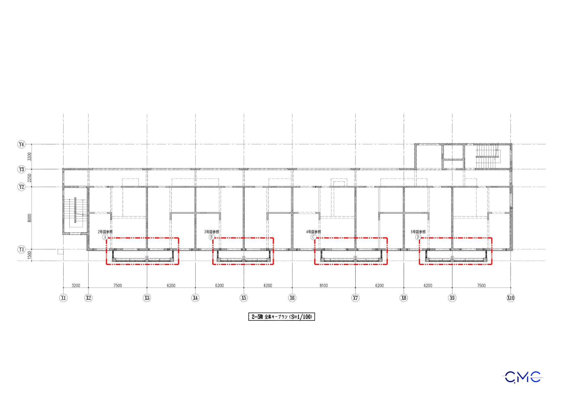
Caption: The overall plan shows the installation locations of aluminum balcony railings by area, helping control the construction scope and installation positions within the project.
Combined Plan and Elevation Drawings – Controlling Dimensions, Levels, and Railing Appearance
After the installation positions are defined in the plan, elevation drawings help clarify the railing shape, height, span, vertical bar spacing, and vertical arrangement of each railing section.
For balcony railings, elevations are particularly important because they directly affect the exterior appearance of the building. If railing sections are inconsistent in height, spacing, or rhythm, the overall façade may lose its visual harmony.
Combined plan and elevation drawings allow the construction team to compare the actual installation location with the intended appearance. As a result, fabrication and installation can be better controlled from the beginning.
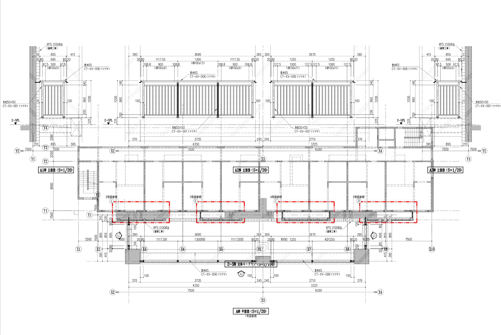
Caption: The plan and elevation drawings help control the installation position, railing length, height, and arrangement of the aluminum balcony railing system.
Detailed Elevation Drawings – Ensuring Consistency Between Railing Sections
In multi-story residential buildings, balcony railings are often repeated in many locations. Therefore, detailed elevation drawings must clearly show each railing section, including its length, post positions, vertical bars, horizontal members, and end points.
Consistency between railing sections helps the building façade look cleaner and more professional. At the same time, detailed drawings also help the fabrication workshop prepare materials and produce components according to the required dimensions.
For aluminum railing systems, even a small deviation in bar spacing or connection position can affect the actual installation process. That is why detailed elevation drawings are an essential part of the construction drawing set.
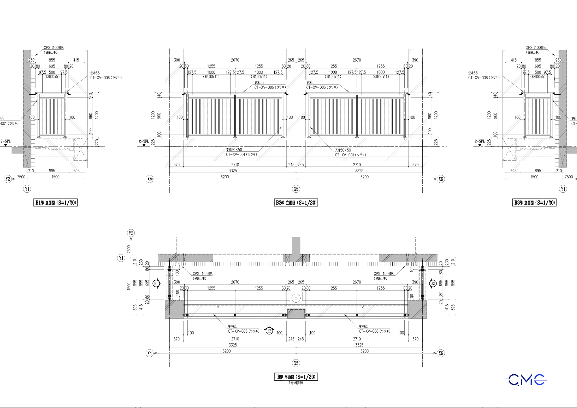
Caption: The detailed elevation drawing shows railing height, length, span arrangement, and vertical bar layout, helping ensure consistency during fabrication and installation.
Typical Detail Areas – Clarifying Key Positions That Require Careful Control
During the development of aluminum balcony railing drawings, some areas require more careful control, such as starting points, ending points, wall-adjacent locations, column connections, joint positions, or areas with dimensional changes.
These areas are often highlighted or shown separately in the drawings so that the construction team can easily recognize them. Separating important detail areas helps reduce misunderstanding, especially when the project includes many repeated railing sections that are similar but not completely identical.
This also makes the drawing set more practical, not only for design presentation but also for direct construction support on site.
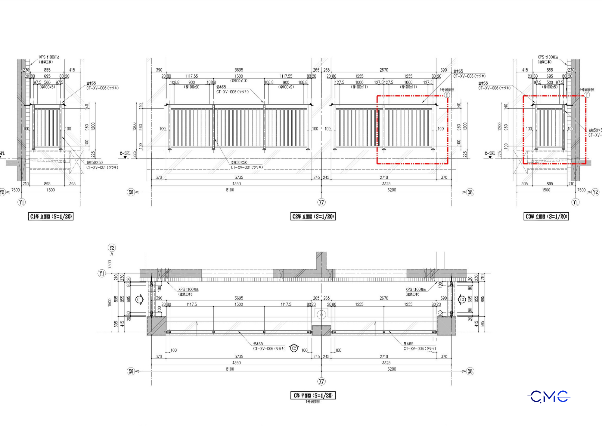
Caption: This drawing shows typical detail areas that require careful control, such as start points, end points, wall-adjacent sections, and railing connection positions.
Section Drawings and Connection Details – The Key to Secure Installation
If the plan drawing defines the position and the elevation drawing controls the appearance, then section drawings and connection details determine whether the railing can be installed correctly in reality.
Section drawings show the relationship between the railing, balcony floor, wall, finishing layers, and surrounding structural elements. Meanwhile, connection details explain the fixing method, anchors, brackets, connecting members, drill hole positions, and how the railing system is secured to the structure.
For aluminum balcony railings, connection details must be clearly presented to ensure that the completed railing system is stable, safe, and visually clean. This information is especially important for both the fabrication workshop and the installation team.
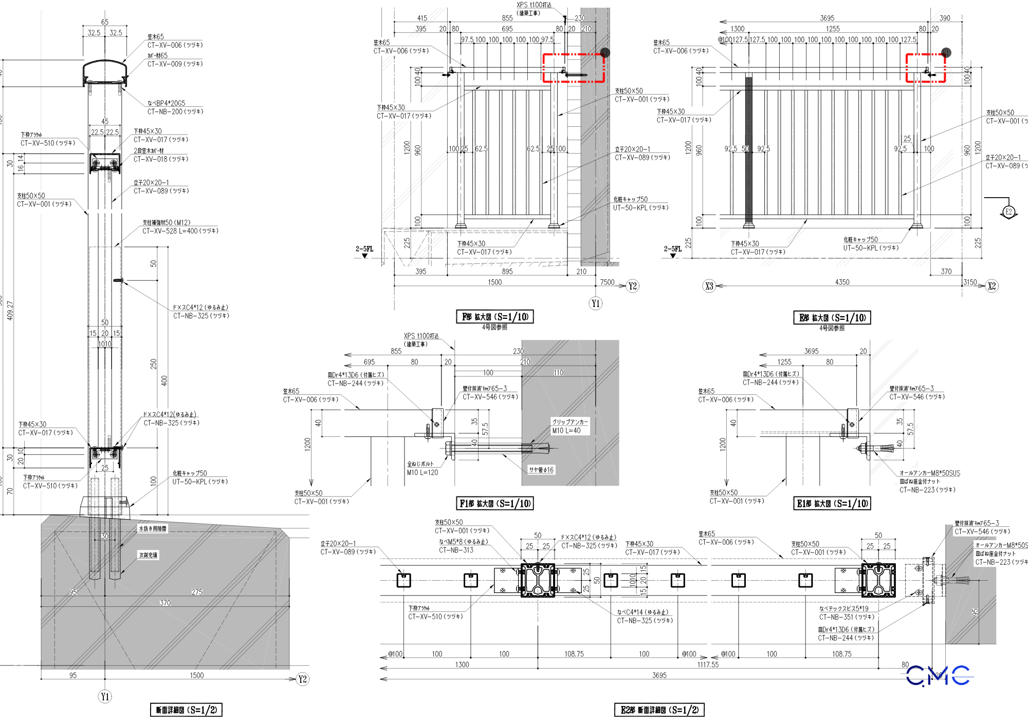
Caption: Section drawings and connection details show the railing structure, anchor positions, fixing method, aluminum members, and technical information required for actual construction.
Why Aluminum Balcony Railing Drawings Need to Be Professionally Developed
A professionally developed aluminum balcony railing drawing set brings many practical benefits to a project.
First, the drawings help reduce construction errors. When dimensions, positions, levels, and connection details are clearly shown, the construction team can install the railing correctly from the beginning, minimizing cutting, adjustment, and rework on site.
Second, the drawings help optimize the fabrication process. The workshop can use the drawings to calculate materials, prepare components, and fabricate details according to the required specifications.
Third, the drawings improve the finishing quality of the project. The installed railing system will be more consistent, more secure, and better aligned with the overall architectural design.
Finally, clear technical drawings make inspection, approval, and handover easier. The client, supervisor, and construction team all have the same technical basis for checking the final installation quality.
CMC Architects Vietnam – Supporting Every Detail in Technical Drawings
CMC Architects Vietnam specializes in developing technical drawings for steel works and architectural metal components, including railings, handrails, steel stairs, technical ladders, steel frames, panels, louvers, and connection details for fabrication and construction.
With strong experience in AutoCAD 2D and detailed technical drawing development, CMC Architects Vietnam aims to create drawing sets that are clear, easy to read, easy to check, and suitable for real construction conditions.
For the scope of aluminum balcony railings, we focus on controlling key information such as plans, elevations, sections, connection details, anchor positions, component dimensions, and consistency between floors. Each drawing is developed with the goal of making construction more accurate, safer, and more professional.
Conclusion
Aluminum balcony railings are an important element in residential buildings. They are directly related to user safety, exterior aesthetics, and the overall finishing quality of the project.
A good drawing set does not simply show dimensions. It also creates an effective connection between design, fabrication, construction, and quality inspection.
In your opinion, what is the most important factor in aluminum balcony railing drawings: a clear plan, detailed elevations, complete sections, or accurate connection details?
Share your thoughts with CMC Architects Vietnam and let’s discuss how to develop more effective technical drawings for real construction projects.
Contact Information
CMC Architects Vietnam
Website: https://www.cmcarchitects.com/
Hotline: 0936361299