In modern construction projects, the generator room is always a technical area that requires a high level of accuracy, especially for items related to electrical systems, cable pits, technical trenches, and protective covers that support operation and maintenance. One detail that may look simple but plays an important role is the electrical cable pit cover for the generator room.
If the drawing is not clearly presented, or if it does not include sufficient information about location, dimensions, elevation, materials, and connection details, the fabrication and installation process may face many issues. These problems can affect construction progress, site coordination, and future maintenance work.
With experience in developing technical drawings using AutoCAD 2D, CMC Architects Vietnam focuses on creating clear, practical, and easy-to-read shop drawings that closely support fabrication teams, installation teams, and site engineers.Image alt text: Electrical cable pit cover plan drawing for generator room
What Is an Electrical Cable Pit Cover for a Generator Room?
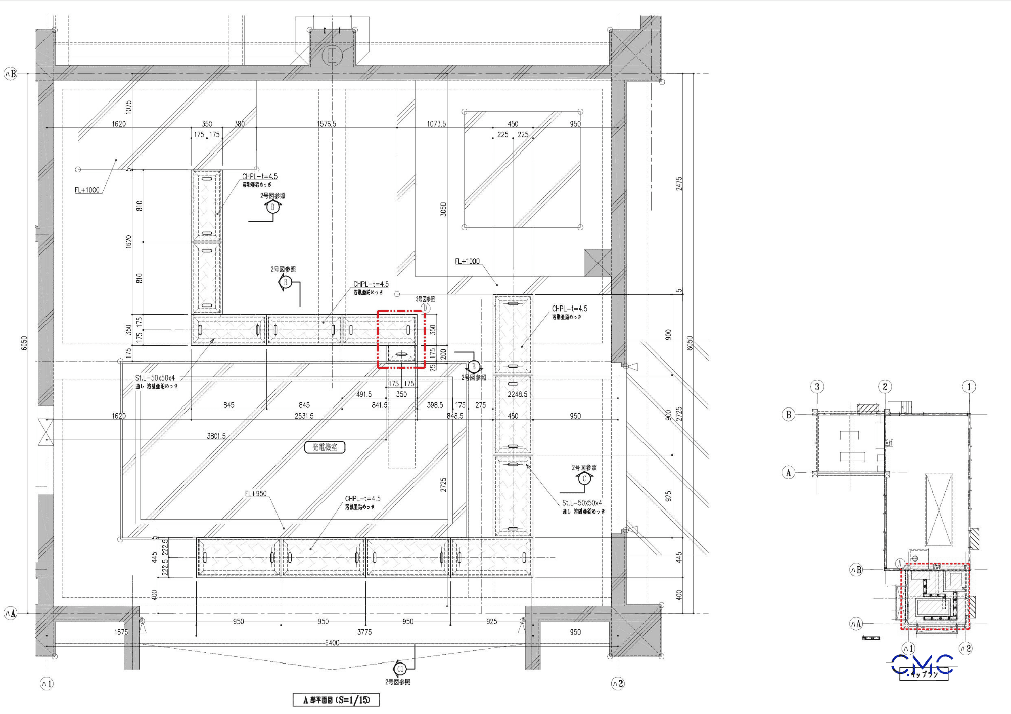
An electrical cable pit cover is used to cover technical pits, cable trenches, or cable connection areas inside a generator room. This item helps protect the electrical cable system while ensuring safety during operation, inspection, and maintenance.
In a generator room environment, every technical detail must be carefully controlled. The cable pit cover must not only match the required dimensions but also ensure strength, convenient opening for inspection, and proper coordination with the finished floor level and surrounding equipment.
A good shop drawing set should clearly show:
- The installation location of the electrical cable pit cover.
- Overall dimensions and detailed component dimensions.
- Finished floor elevation and related technical levels.
- Materials used for the cover plate, supporting frame, and reinforcement details.
- Opening direction, handle position, or access holes if required.
- Welding, fixing, and connection details with the surrounding structure.
Why Do Electrical Cable Pit Cover Shop Drawings Need to Be Accurate?
For technical items inside a generator room, even a small drawing error can create significant problems during actual construction. If the cover does not match the pit size, does not align with the prepared opening, or is not coordinated with the floor level, the installation team may need to cut, modify, or refabricate components on site.
This not only increases construction costs but may also delay the project schedule. Especially in areas related to electrical systems, inaccurate installation can make future inspection, maintenance, and operation more difficult.
Detailed drawings help all related parties control:
- Pit dimensions and cover dimensions.
- Position of the steel supporting frame.
- Spacing between connection details.
- Cover plate and reinforcement structure.
- Removable design for maintenance access.
- Coordination between architectural, structural, and electrical drawings.
Shop Drawing Plan – Defining the Correct Installation Location
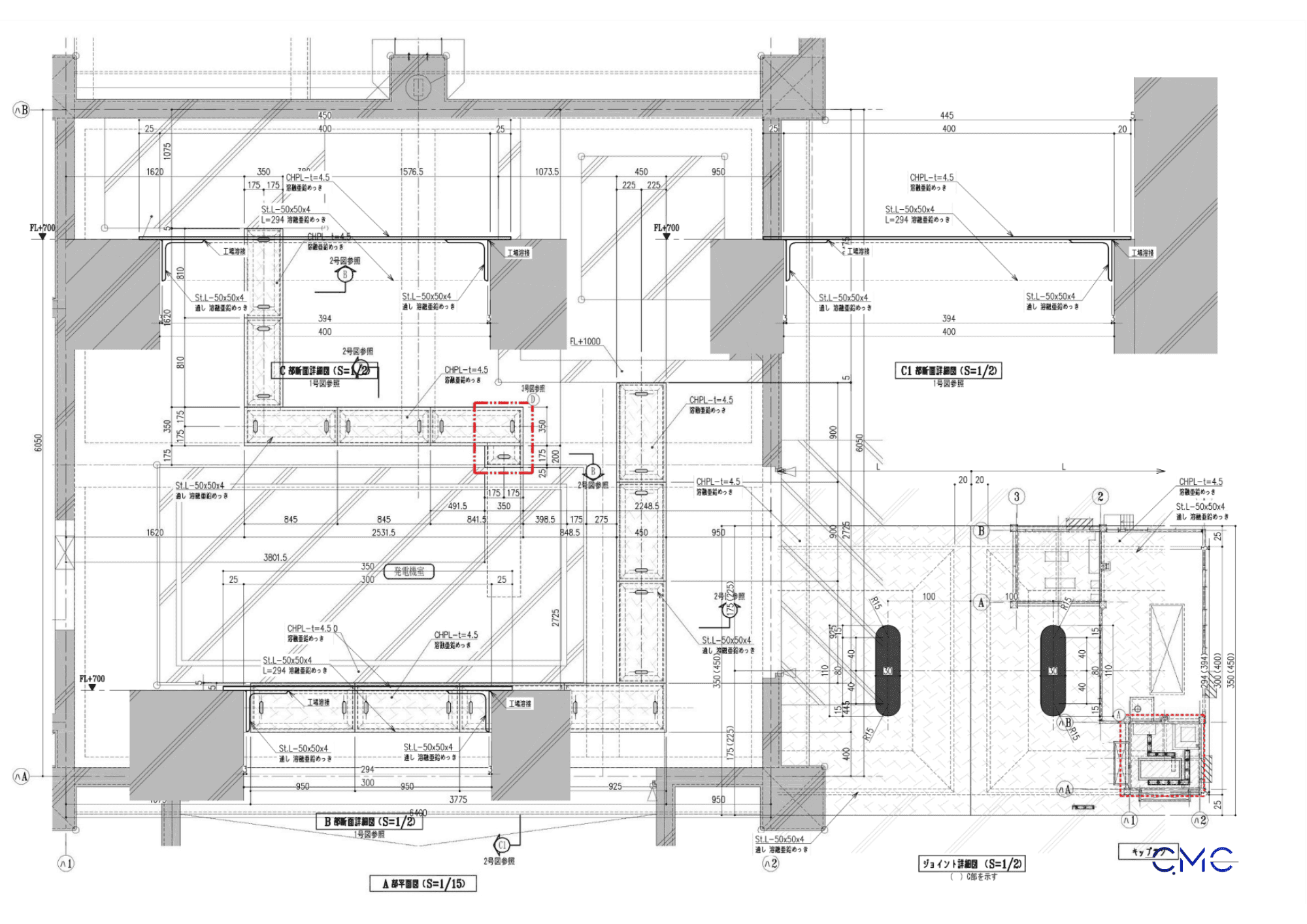
The plan drawing is the first important part of the shop drawing set. Through the plan, the construction team can accurately identify the position of the electrical cable pit cover inside the generator room, including its relationship with walls, columns, equipment, and surrounding technical areas.
In the drawings developed by CMC Architects Vietnam, the pit cover area is clearly shown with outlines, dimensions, elevations, and reference symbols linked to sections and enlarged details. This helps the drawing reader easily follow the information from the overall layout to each technical detail, reducing the risk of misunderstanding during site installation.
A clear plan drawing helps to:
- Accurately locate the item to be installed.
- Check its coordination with the generator room layout.
- Minimize discrepancies between drawing and site conditions.
- Support inspection and handover after installation.
- Provide a technical basis for sections and detailed drawings.
Section Drawings – Clarifying Structure and Elevation
If the plan drawing defines the location, the section drawing explains the vertical structure of the item. For an electrical cable pit cover, the section must clearly show the cover plate thickness, steel supporting frame, welding position, installation gap, floor elevation, and relationship with the surrounding structure.
This is a very important part of the drawing set because it helps the construction team understand the correct installation method, especially in areas that require precise finished floor levels. If the cover elevation is not coordinated with the floor surface, it may affect operational safety or create difficulties when moving equipment.
In this drawing set, the sections are presented with specific dimensions, allowing the fabrication workshop and installation team to work from the same technical information.
Fabrication Details – A Key Factor in Installation Quality
A complete shop drawing set cannot be missing fabrication details. This part helps the workshop clearly understand each component that needs to be fabricated, including cover plate dimensions, steel frame, access holes, welding positions, and reinforcement details.
For an electrical cable pit cover, fabrication details must be developed clearly to ensure strength, ease of removal, and suitability for real site conditions. Details such as pull holes, access openings, folded edges, base plates, or supporting members must be accurately shown in the drawing.
When the fabrication drawing is clear, the production process becomes smoother, reducing the need for repeated clarification or post-fabrication correction.
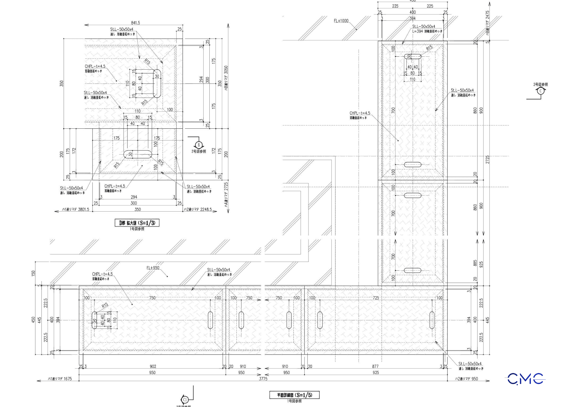
Image alt text: Electrical cable pit cover fabrication detail drawing for generator room
Controlling Materials and Connections in the Drawing
Materials and connections directly affect the durability and performance of the item. For an electrical cable pit cover, the drawing should clearly specify the steel type, plate thickness, steel angle size, welding method, surface treatment, and finishing requirements.
Clear material information helps the fabrication workshop prepare the correct material type and specifications, avoiding production mistakes. At the same time, technical notes on the drawing help the installation team understand the requirements for connections, welding locations, and on-site fixing methods.
CMC Architects Vietnam always focuses on presenting drawings in a way that is easy to check, easy to compare, and practical for actual construction work.
The Role of AutoCAD 2D in Technical Drawing Development
For detailed items such as electrical cable pit covers, AutoCAD 2D remains a highly effective tool for presenting technical information. Linework, dimensions, section symbols, and enlarged details can be shown clearly and directly, helping drawing users quickly understand what needs to be fabricated and installed.
AutoCAD 2D drawings are highly useful for:
- Steel fabrication workshops.
- On-site installation teams.
- Engineers responsible for inspection and approval.
- Quality control teams.
- Technical documentation and handover.
With a clear drawing layout, 2D drawings help reduce confusion, minimize mistakes, and improve coordination between all parties involved in the project.
CMC Architects Vietnam – Supporting Projects with Accurate Technical Drawings
CMC Architects Vietnam specializes in developing technical drawings, fabrication drawings, and shop drawings for various construction items such as railings, handrails, steel stairs, ladders, panels, louvers, door frames, technical covers, and architectural metal details.
With a working approach based on clarity, precision, and practicality, CMC Architects Vietnam focuses on creating drawing sets that are easy to read, easy to build, and highly applicable on site.
We understand that a good drawing is not only well-presented but must also help the construction process run more smoothly, reduce errors, and support effective quality control.
Conclusion
Electrical cable pit cover shop drawings for generator rooms are important technical documents that help control location, dimensions, elevation, materials, and connection details before fabrication and installation. For technical areas such as generator rooms, drawing accuracy should never be underestimated.
Through clear and well-structured shop drawings, CMC Architects Vietnam aims to provide technical solutions that better support construction, operation, and maintenance.
Are you looking for technical drawings for steel items, architectural metal components, or detailed construction elements? Contact CMC Architects Vietnam for accurate, practical, and professional drawing solutions.