In commercial buildings, office towers, service centers, and public facilities, the escalator area is always a high-traffic zone that requires strict attention to safety, durability, and visual quality. For that reason, the escalator glass handrail frame and safety barrier system must not only look clean and modern, but also meet precise technical requirements during fabrication and on-site installation.
To ensure smooth execution, technical drawings must clearly present the installation location, overall dimensions, floor plans, elevations, sections, frame structure, glass details, base plates, connection points, and all necessary specifications for fabrication and site assembly.
With strong experience in AutoCAD 2D technical drawing development, CMC Architects Vietnam provides clear, accurate, and practical fabrication and installation drawings that support both workshop production and construction site execution.
What Are Escalator Glass Handrail Frames and Safety Barriers?
An escalator glass handrail frame is a structural and finishing system used to secure, protect, and complete the areas around escalators. This item usually combines glass panels, metal frames, handrails, base plates, and connection components fixed to the floor or surrounding structures.
Meanwhile, safety barriers help define circulation areas, create protective boundaries, and improve safety control for users. These systems are often installed near escalators, atriums, transition zones, lobby areas, or any space that requires additional protection and guidance.
A professional drawing set should help the fabrication and installation teams clearly understand:
- The installation position of each frame section.
- Overall and detailed dimensions.
- Finished levels and heights.
- Material specifications.
- Glass, frame, handrail, and accessory locations.
- Base plates, bolts, screws, and anchoring points.
- Corner conditions, direction changes, and end details.
Why Fabrication and Installation Drawings Matter for Escalator Areas
Unlike simple decorative items, escalator glass handrail frames and safety barriers are directly connected to areas used by people every day. Therefore, even a small error in dimension, level, or connection detail can affect the construction schedule, final quality, and overall safety of the project.
A detailed fabrication and installation drawing set helps:
- Reduce mistakes during workshop fabrication.
- Guide installation teams to the correct positions.
- Control height, spacing, and finished levels accurately.
- Synchronize information between design, production, and site teams.
- Minimize unexpected issues during installation.
- Support a clearer and more professional inspection process.
Overall Floor Plan – Defining the Exact Installation Scope
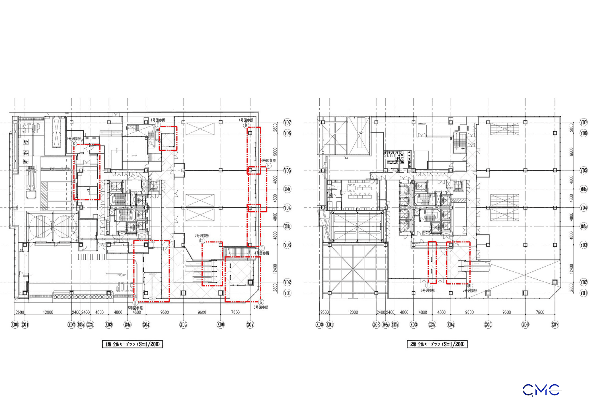
In a technical drawing set, the overall floor plan helps define the full scope of work. For projects with multiple floors, several escalator areas, and different safety barrier locations, the overall floor plan allows the reader to quickly understand where the work will be carried out.
Through the floor plan, the technical team can review:
- Installation positions by floor.
- Escalator areas requiring glass handrail frames.
- Safety barrier sections according to building grids.
- Positioning dimensions based on the architectural layout.
- The relationship between metalwork items and surrounding spaces.
This becomes the foundation for developing more detailed drawings, including enlarged plans, elevations, sections, and connection details.

Detailed Floor Plan – Controlling Each Installation Area
After defining the overall scope, the detailed floor plan clarifies each specific installation area. This is especially important for items with multiple frame sections, connection points, and interfaces with walls, columns, floors, or surrounding architectural elements.
In the detailed floor plan, dimension lines, grid references, and connection symbols must be clearly presented so that the installation team can directly compare the drawing with actual site conditions. This helps control the installation process more effectively and reduces the risk of incorrect positioning or alignment errors.
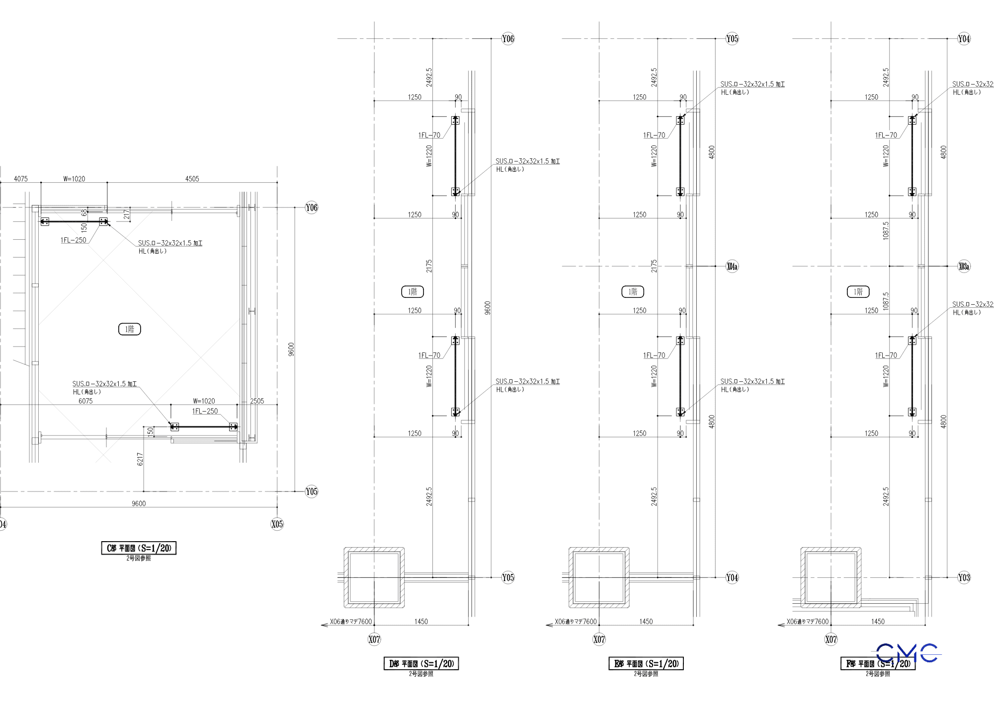
Image alt text: Detailed floor plan of safety barriers and escalator glass frames
Escalator Area Drawings – Clarifying Direction and Connection Points
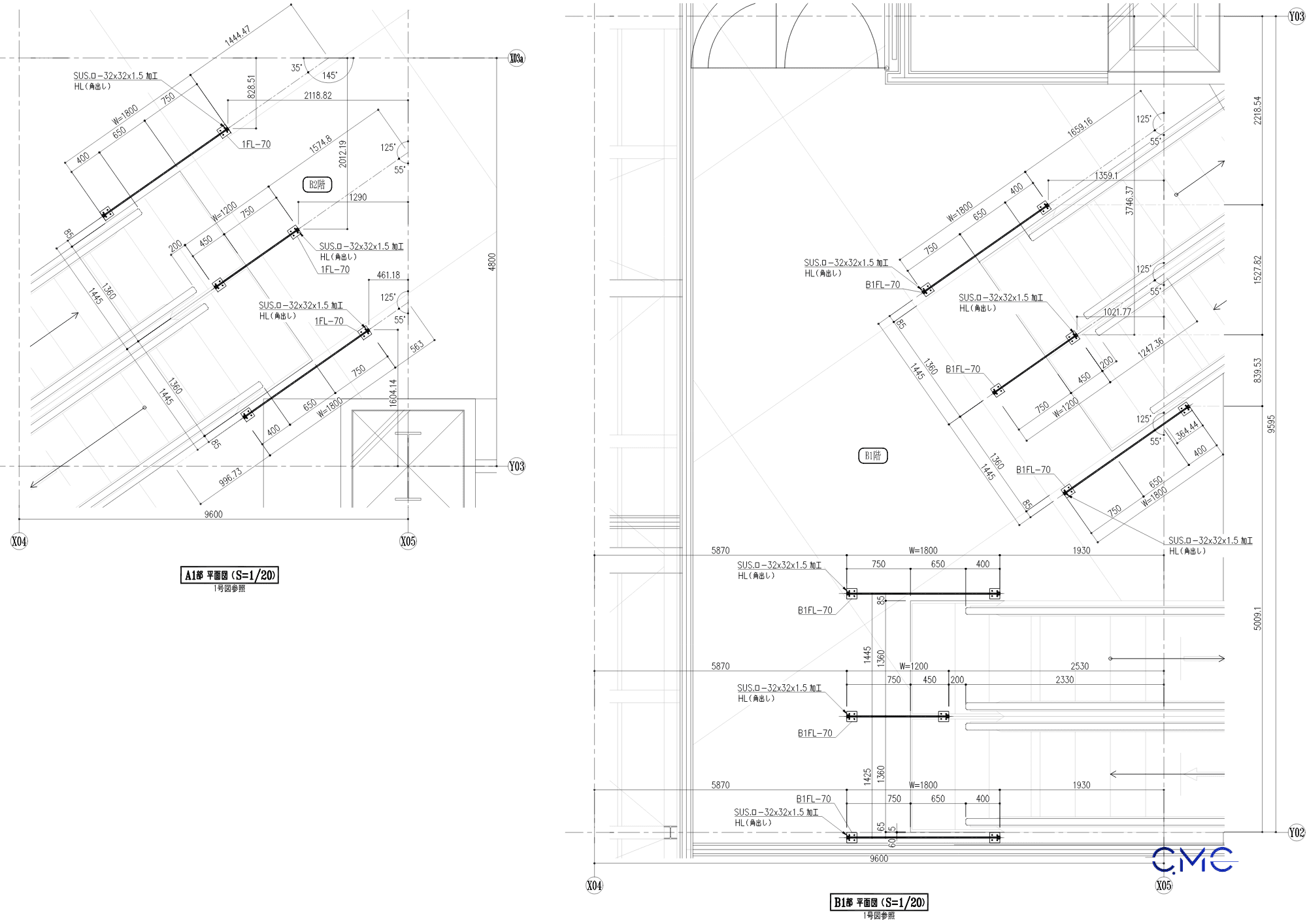
Escalator areas are often more complex than standard straight sections. The frames may follow inclined directions, change angles, or connect with finished architectural elements. Therefore, the drawings must clearly show the direction, length of each section, handrail position, and installation spacing.
A clear drawing allows the fabrication team to understand the structure of each section before production. It also helps the installation team check the level, alignment, and position during on-site assembly.
Elevation Drawings – Showing Height and Final Appearance
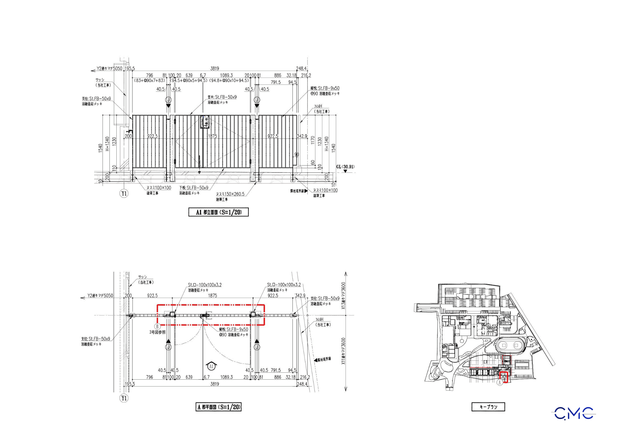
Elevation drawings help show the visual appearance of the item after installation. For escalator glass handrail frames and safety barriers, elevations should clearly present glass height, frame height, handrail position, spacing between components, and the overall proportion of the system.
Clear elevation drawings help:
- Control the finished height.
- Ensure consistency between different sections.
- Reduce errors during frame fabrication.
- Help the client and construction team visualize the completed item.
This is an essential part of any fabrication and installation drawing set for architectural metalwork.
Section Drawings – Explaining the Technical Structure
Section drawings help explain the internal structure of the item. If the floor plan shows the position and the elevation shows the appearance, the section drawing shows how the components are connected.
Important information in section drawings usually includes:
- Metal frame structure.
- Glass thickness.
- Handrail position.
- Gap between glass and frame.
- Connection details to the floor or surrounding structure.
- Installation levels.
- Base plate, bolt, and fixing accessory specifications.
The clearer the section drawing, the smoother the installation process and the easier it becomes to control quality on site.
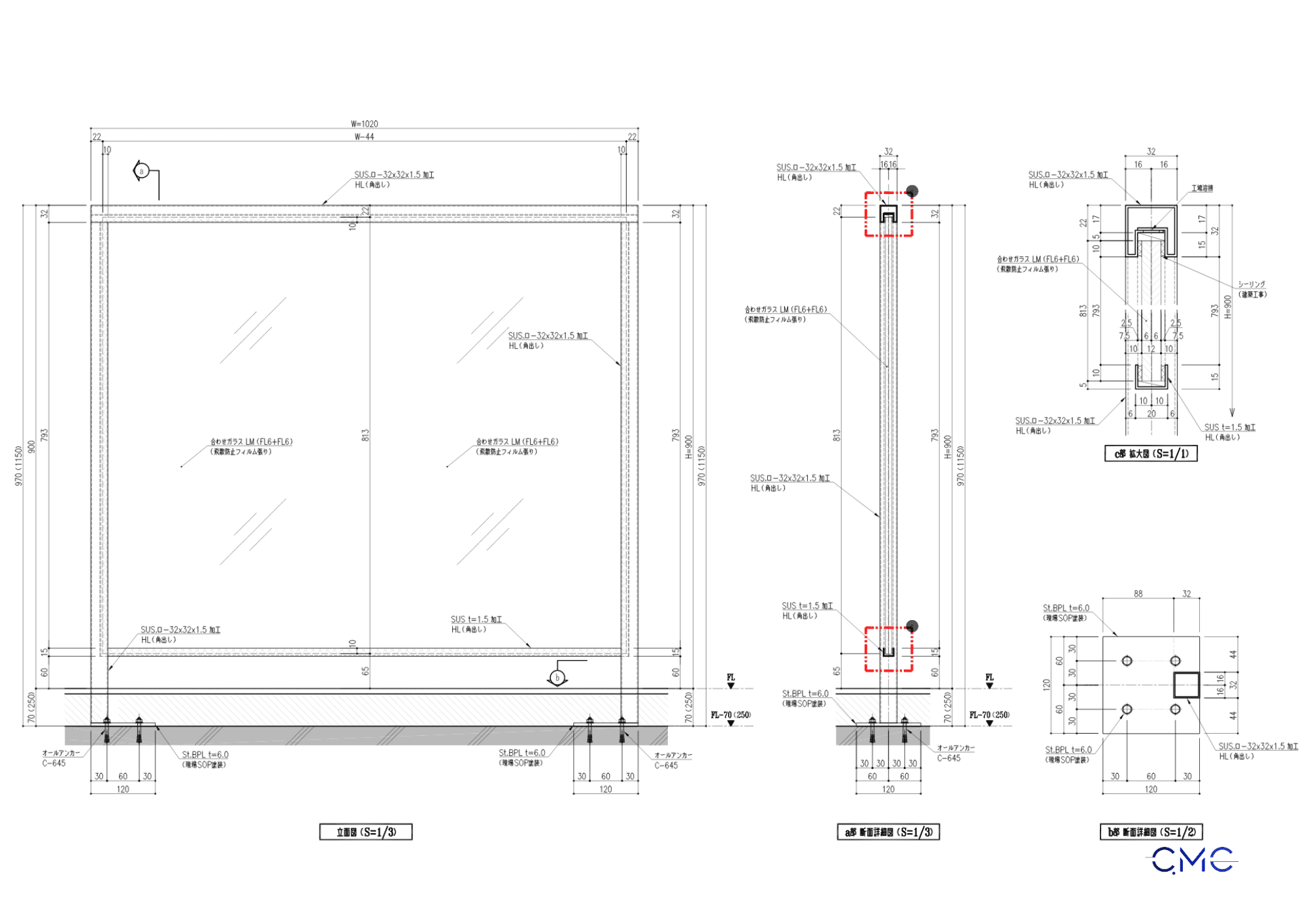
Connection Details – A Key Factor for Safety
For systems using glass and metal frames, connection details have a direct impact on stability and safety. Base connections, fixing plates, bolts, screws, and interfaces with the floor must be clearly shown in the drawings.
A well-developed connection detail helps:
- Improve the stability of the frame system.
- Ensure the glass is fixed correctly.
- Reduce vibration or misalignment during use.
- Help the installation team follow the technical requirements accurately.
- Support inspection and handover after installation.
CMC Architects Vietnam always focuses on presenting connection details in a clear, readable, and practical way for both fabrication and site installation.
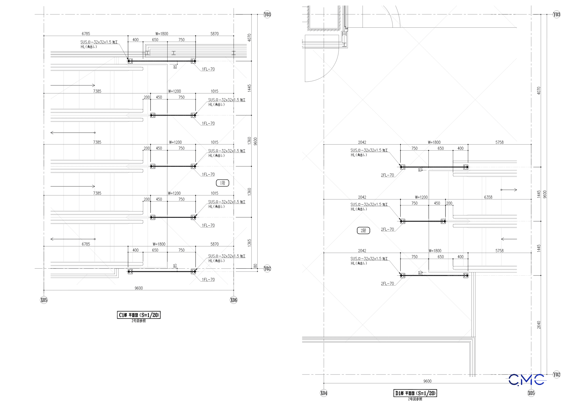
Image alt text: Connection detail drawing for escalator glass handrail frames and safety barriers
The Role of AutoCAD 2D in Fabrication and Installation Drawings
AutoCAD 2D remains an important tool for developing technical drawings for architectural metalwork. With its ability to clearly present linework, dimensions, symbols, technical notes, and enlarged details, AutoCAD 2D helps create practical documents for both workshop fabrication and construction site teams.
For items such as glass handrail frames, safety barriers, railings, steel stairs, ladders, panels, louvers, and metal door frames, AutoCAD 2D drawings help:
- Fabricate components according to accurate dimensions.
- Install each item in the correct position.
- Control connection details.
- Review and revise information efficiently when needed.
- Create clear technical documentation for handover.
CMC Architects Vietnam – Clear and Practical Technical Drawing Solutions
CMC Architects Vietnam focuses on developing technical drawings, fabrication drawings, and installation drawings for steel, glass, stainless steel, aluminum, and architectural metalwork items.
We understand that a good drawing set is not only about clean layout presentation. More importantly, it must be accurate, easy to read, and practical enough to support real fabrication and construction work.
For each project, CMC Architects Vietnam focuses on:
- Clear drawing layout.
- Complete dimensioning.
- Easy-to-understand connection details.
- Clear material information.
- Drawings suitable for real site conditions.
- Support for fabrication, installation, and inspection.
Conclusion
Fabrication and installation drawings for escalator glass handrail frames and safety barriers are essential technical documents that help control the entire process from design and production to on-site installation. A clear drawing set helps reduce errors, save time, optimize costs, and improve the final quality of the project.
If you need technical drawings for escalator areas, glass handrails, safety barriers, railings, steel stairs, or other architectural metalwork items, CMC Architects Vietnam is ready to support your project with accurate, professional, and practical drawing solutions.
What type of technical drawing do you need for your next project? Contact CMC Architects Vietnam to discuss the most suitable solution.